42 draw the shear diagram for the beam. mastering engineering
Draw the shear and moment diagrams for the beam, and ... Draw the shear and moment diagrams for the beam, and determine the shear and moment throughout the beam as functions of x. Search. R e w a r d s . from HOLOOLY. HOLOOLY . A D S. HOLOOLY . T A B L E S. ... Draw the shear and moment diagrams for the beam, and determine the shear and moment throughout the beam as functions of x. Step-by-Step. 6-10 Rules of Shear Force Diagram (Part 3) - Coursera We will get to the most important part, which is analyzing frames and beams to calculate their internal forces and to draw axial, shear and moment diagrams. Contrary to most textbook presentations, we will adopt a notation that is universally adopted by engineers when using moment diagrams. 6-8 Rules of Shear Force Diagram (Part 1) 2:15.
Job leading course on Drafting and Design Using Revit ... Determining the bending moment and shear force diagrams of beams; ... Analyze the beam & draw bending moment and shear force diagrams. In this project, the students need to determine the loading on the beam of a building whose data will be given, analyze the beams, and draw bending moment and shear force diagrams. ... We have sent an email with ...

Draw the shear diagram for the beam. mastering engineering
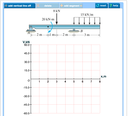
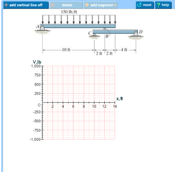
Bending moment - pearsoncmg.com Use the solutionAppletFlash answer type to create items that require students to draw axial force, shear force, and bending moment diagrams of a loaded beam. For accessible bending moment content: Use the Simple Editor engineering - bending moment answer type to create questions for students who use a keyboard or supported screen reader. (Solved) - Draw the shear diagram for the beam. Begin by ... 1 Answer to Please sketch the shear and moment diagram Draw the shear diagram for the beam. Begin by placing the lines of discontinuity. Place the appropriate function between the lines of discontinuity, ensuring the endpoints have the correct values. Draw the shear diagram for the beam. Click on "add | Chegg.com Engineering; Mechanical Engineering; Mechanical Engineering questions and answers; Draw the shear diagram for the beam. Click on "add vertical line off" to add discontinuity lines. Then click on "add segment" button to add functions between the lines. Note 1 - Make sure you place only one vertical line at places that require a vertical line.
Draw the shear diagram for the beam. mastering engineering. 6-9 Rules of Shear Force Diagram (Part 2) - Internal Force ... Video created by Universidade de Ciência e Tecnologia de Hong Kong for the course "Mastering Statics". We will get to the most important part, which is analyzing frames and beams to calculate their internal forces and to draw axial, shear and ... ANSWER Correct Part B Draw the shear diagrams Click on add ... Only typed answer no handwritten please Problem 7.84 Draw the shear diagram for the beam. Follow the sign convention. (Figure 1) Click on "add vertical line off" to add discontinuity lines. Shear force and bending moment questions - pearsoncmg.com Answer shear force & bending moment questions by drawing on a graph. Refer to the provided diagram as you work on the graph to answer the question. If the graph is below the diagram: The lines of discontinuity will be along the y-axis. If the graph is to the right of the diagram: The lines of discontinuity will be along the x-axis. Mastering Shear Force and Bending Moment Diagrams [9.6/10] Before we get into the detail of shear force and bending moment diagrams, first we need to do a little housekeeping. We'll clarify a few assumptions that apply to our analyses and make sure you can determine support reactions for statically determinate structures. Section 2: Understanding internal bending moments.
Mastering Shear Force & Bending Moment Diagrams ... You will be fully competent in drawing shear force and bending moment diagrams for statically determinate beams and frames. You will understand the relationship between external loading and the shear forces and bending moments they induce. You will understand the link between internal stresses and their shear force and bending moment resultants. Pearson Education, Mastering Engineering | Pearson Graphical Answer Type problems enable students to practice their problem-solving skills by drawing shear and bending moment diagrams from the free-body diagram of a beam in Mastering Engineering. The Vector Drawing Tool in Mastering Engineering helps students learn how to visualize answers just like they were working a problem out by hand. Answered: Draw the shear diagram for the beam… | bartleby Engineering Civil Engineering Q&A Library Draw the shear diagram for the beam Click on "add vertical line ofr to add discontinuity lines. Then click on "add segment" button to add functions between the lines. Note 1- Make sure you place only one vertical line at places that require a vertical line. The Ultimate Guide to Shear and Moment Diagrams ... 4.0 Building Shear and Moment Diagrams. In the last section we worked out how to evaluate the internal shear force and bending moment at a discrete location using imaginary cuts. But to draw a shear force and bending moment diagram, we need to know how these values change across the structure.
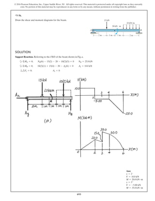
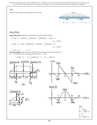
Drawing Shear and Moment Diagrams Example ... - YouTube this is a detailed example of shear and moment diagrams, i recommend skipping around to the sections shown below if you already have a feel for the subject:i... Chapter 7 No portion of this material may be reproduced, in any form or by any means, without permission in writing from the publisher. 7-46. Draw the shear and moment diagrams for the beam (a) in terms of the parameters shown; (b) set L = 12 ft. a = 5 ft,P = 800 lb, SOLUTION (a) For Ans. a Ans. For Ans. a Ans. (Solved) - Draw the shear diagram for the beam. Follow the ... Draw the shear diagram for the beam. Follow the sign convention. (Figure 1) Click on "add vertical line off" to add discontinuity lines. Then click on "add segment" button to add functions between the lines. Note - The curve you choose from the drop-down is only a pictorial representation of a real quadratic/cubic curve. Draw the shear and moment diagrams for the beam a in terms ... View Homework Help - HW 5 SOLNS from CE 240 at California State University, Northridge. CE 240 HW #5 SOLUTIONS 1. FALL 2016 Draw the shear and moment diagrams for the beam (a) in terms of the
ANSWER Correct Part E Determine the moment as a function of ...
Answered: Draw the shear and moment diagram for… | bartleby Q: Problem 3 Draw the shear and bending-moment diagrams for the beam. 4 kN M = 2 kN m A -2 m -2 m 2 m. A: Click to see the answer. question_answer. Q: In an ammonia refrigeration system, the pressure in the evaporator is 251 kPaa, and the ammonia at…. A: Given:Pe=251 kPax1=0.1511x2=0.95m=4.56 kg/min.
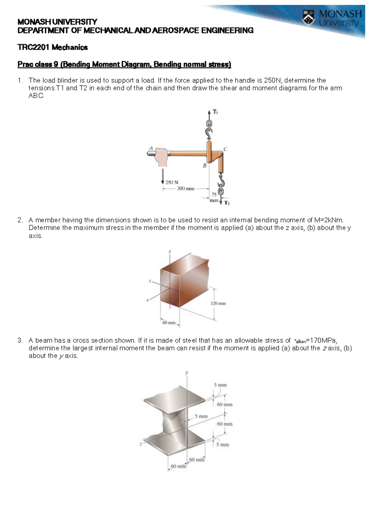
Problem Sheet 9 - week 9 questions - MONASH UNIVERSITY ...
Mastering Engineering Graphical Answer Type Video ... Mastering Engineering Graphical Answer Type Video Transcript. ... let's take a look at the Shear and Bending Moment and the Mohr's circle tutorial homework problems. In this tutorial, students will practice their problem solving skills by drawing shear and bending moment diagrams from the free-body diagram of a beam.
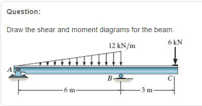
Solved Question: Draw the shear and moment diagrams for the ...
Mastering Shear Force and Bending Moment Diagrams - Udemy Mastering Shear Force and Bending Moment Diagrams. Civil Engineering Essentials - Your complete roadmap to mastering these structural analysis skills ... What you'll learn. You will be fully competent in drawing shear force and bending moment diagrams for statically determinate beams and frames.
Solved Draw the shear diagram for the beam. Draw the moment ...
6-7 Introduction to Axial, Shear and Bending Moment Diagram We will get to the most important part, which is analyzing frames and beams to calculate their internal forces and to draw axial, shear and moment diagrams. Contrary to most textbook presentations, we will adopt a notation that is universally adopted by engineers when using moment diagrams. 6-6 Sign convention: A critical review 7:18.

Draw the shear and moment diagrams for the beam.
(Solved) - Draw the shear diagram for the beam. Follow the ... 1 Answer to Draw the shear diagram for the beam. Follow the sign convention. (Figure 1) Click on "add vertical line off" to add discontinuity lines. Then click on "add segment" button to add functions between the lines. Note 1 - The curve you choose from the drop-down is only a pictorial representation of a...

Understanding Sign Conventions in Structural Analysis ...
Features for Students | Mastering Engineering | Pearson Graphical Answer Type in Mastering Engineering. Watch how you can practice problem-solving skills by drawing shear and bending moment diagrams from the free-body diagram of a beam in Mastering Engineering. Read a transcript of this video.
6.2 Shear/Moment Diagrams – Engineering Mechanics: Statics
PDF Multimedia Tutorials For Drawing Shear Force And Bending ... mastering each of the varied methods (or often any single method) for construction, and with ... Shear Force diagram, and one for drawing the Bending Moment diagram. Figure 1 shows the ... free body diagram of the full beam, a free body diagram of a partial beam, and the bending moment diagram. The items in gray on each page in each tutorial ...

Solved) - Draw the shear and bending moment diagrams for the ...
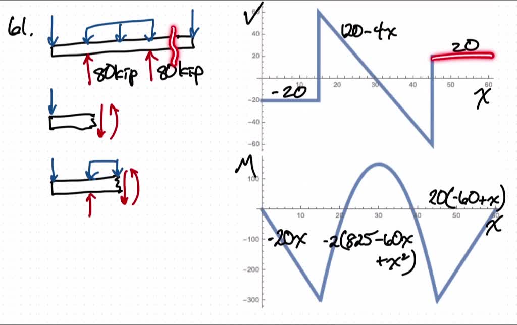
How to Draw Shear Diagrams | ReviewCivilPE Shear diagrams always begin and end at zero, with all of the forces on the member shown in between.Starting from the left, the first force you come across is the 10 lb downward force at the left end. This is the first point of data, draw a line from zero to negative 10.. Continuing on the next force is 21.67 lb upward at the A support.
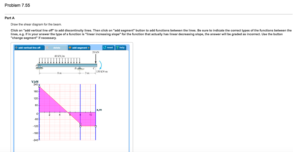
Solved Problem 7.55 Part A Draw the shear diagram for the ...
6-13 Rules of Bending Moment Diagram - Internal Force ... We will get to the most important part, which is analyzing frames and beams to calculate their internal forces and to draw axial, shear and moment diagrams. Contrary to most textbook presentations, we will adopt a notation that is universally adopted by engineers when using moment diagrams. 6-13 Rules of Bending Moment Diagram 14:54.
Drawing Shear and Moment Diagrams Example- Mechanics of Materials and Statics
Mastering Engineering, Assignment--12--Beams (Engineering ... Assignment12Beams Due: 11:59pm on Tuesday, April 26, 2016 You will receive no credit for items you complete after the assignment is due. Grading Policy Problem 7.52 Part A Select the correct shear diagram for the beam. ANSWER:
Draw the shear and moment diagrams for the beam. - ITProSpt
Draw the shear diagram for the beam. Click on "add | Chegg.com Engineering; Mechanical Engineering; Mechanical Engineering questions and answers; Draw the shear diagram for the beam. Click on "add vertical line off" to add discontinuity lines. Then click on "add segment" button to add functions between the lines. Note 1 - Make sure you place only one vertical line at places that require a vertical line.

Mastering Engineering, Assignment--12--Beams (Engineering ...
(Solved) - Draw the shear diagram for the beam. Begin by ... 1 Answer to Please sketch the shear and moment diagram Draw the shear diagram for the beam. Begin by placing the lines of discontinuity. Place the appropriate function between the lines of discontinuity, ensuring the endpoints have the correct values.

Solved) - Problem 7.85 Part A Draw the shear diagram for the ...
Bending moment - pearsoncmg.com Use the solutionAppletFlash answer type to create items that require students to draw axial force, shear force, and bending moment diagrams of a loaded beam. For accessible bending moment content: Use the Simple Editor engineering - bending moment answer type to create questions for students who use a keyboard or supported screen reader.
6-13 Rules of Bending Moment Diagram - Internal Force ...
![Solved] (a) Draw the shear and bending-moment diagrams for ...](https://s3.amazonaws.com/si.question.images/image/images14/1221-P-M-K(1994).png)
Solved] (a) Draw the shear and bending-moment diagrams for ...

ENGINEERING MECHANICS STATICS Pages 351-400 - Flip PDF ...
Understanding Sign Conventions in Structural Analysis ...
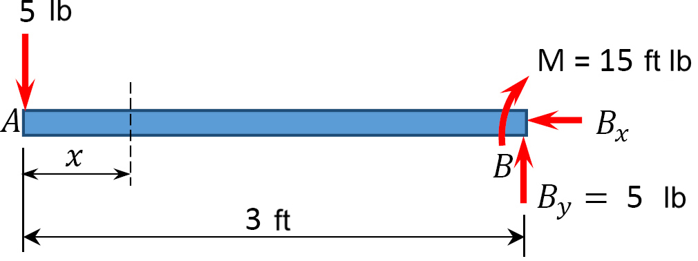
Solved) - Draw the moment diagram for the beam. Follow the ...
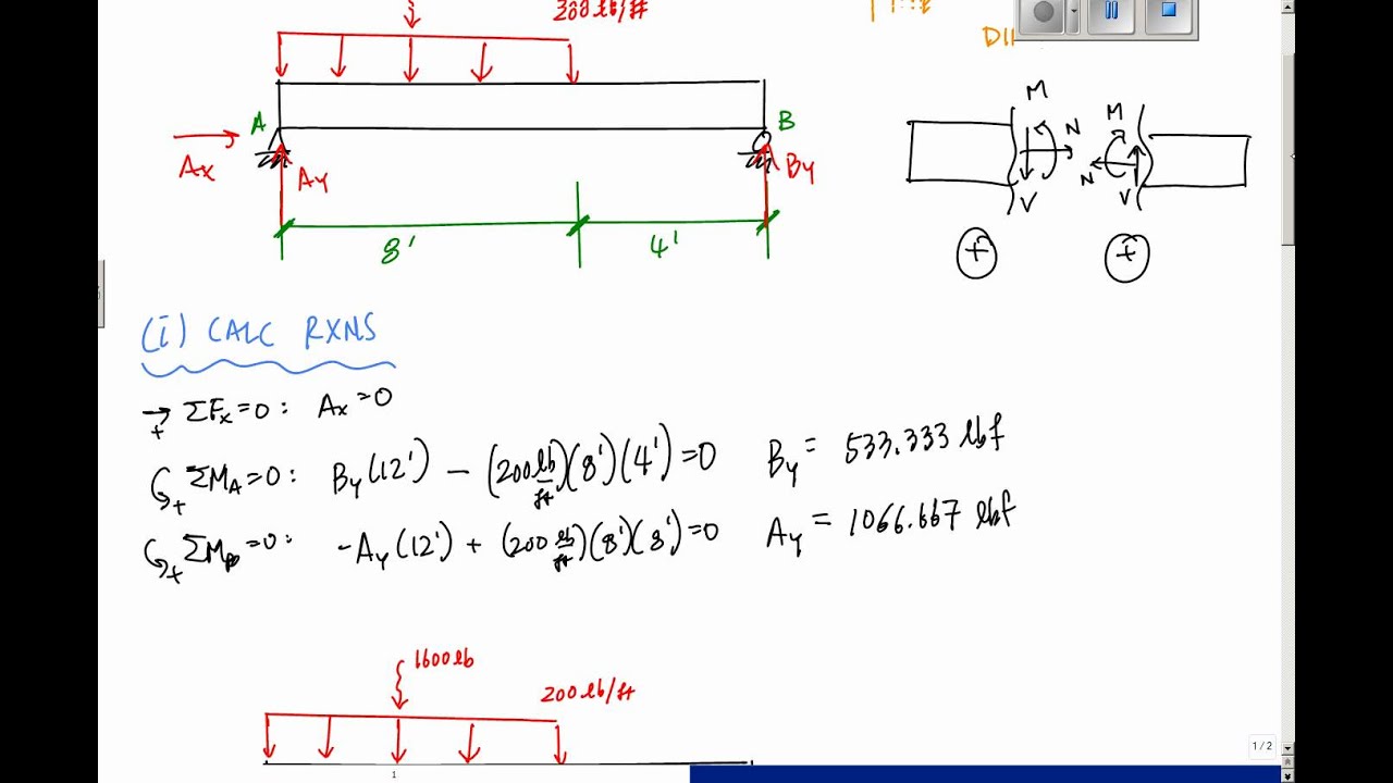
Chapter 7
Chapter 7

Draw the shear and moment diagrams for the beam

Solved) - Draw the shear and moment diagrams for the beam ...
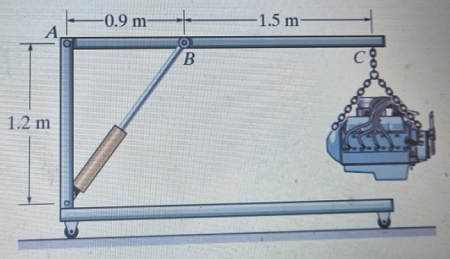
The engine crane is used to support the engine, which has a ...

Solved) - Draw the shear and moment diagrams for the beam ...
Statics - TAM 210 & TAM 211
Solved problem 7.80 part A draw the shear diagram for the ...
Solved Shear and Bending Moment Diagrams Learning Goal ...

Solved: Chapter 5 Problem 10P Solution | Mechanics Of ...

Solved 7.78 Draw the shear and moment diagram for the beam ...
Answered: Draw the shear and moment diagrams for… | bartleby

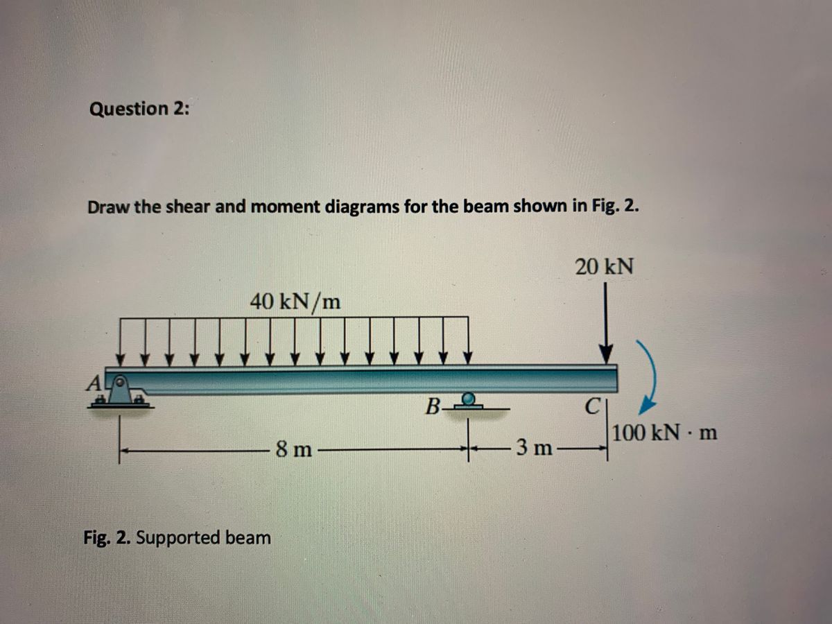
Draw the shear and moment diagrams for the beam shown in Fig ...
Solved Part A Draw the shear diagram for 0 ≤ x ≤ Part ...
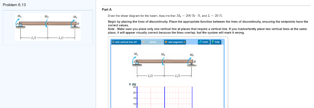
Solved Problem 6.13 Part A Draw the shear diagram for the ...
Multimedia Tutorials For Drawing Shear Force And Bending ...
![[3/3] Mastering Shear Force and Bending Moment Diagrams - Lecture 13: Worked Example #4](https://i.ytimg.com/vi/moVT-z1AKjU/hqdefault.jpg)
[3/3] Mastering Shear Force and Bending Moment Diagrams - Lecture 13: Worked Example #4
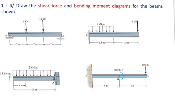
Solved) - Draw the shear force and bending moment diagrams ...

Features for Educators | Mastering Engineering | Pearson
Multimedia Tutorials For Drawing Shear Force And Bending ...
Solved Draw the shear diagram for the beam. Draw the Moment ...
Chapter 7
Multimedia Tutorials For Drawing Shear Force And Bending ...
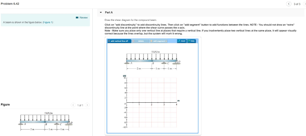
Solved Problem 6.42 3 of 3> Part A Review Draw the shear ...


Comments
Post a Comment