40 gm vss wiring diagram
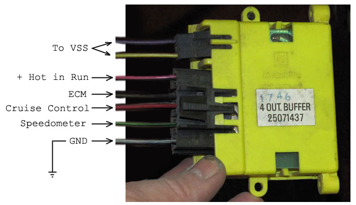
The other 2 are not used but the VSS wire is the brown wire located on the larger of the 2 connectors not being used. Definition: V ehicle Speed Sensor (VSS) via Crutchfield. In addition to the standard power and ground leads, remote-mount navigation (and even some in-dash units) systems connect to a vehicle’s Vehicle Speed Sensor (VSS) wire. Gm Speed Sensor Wiring | Wiring Diagram – 2 Wire Speed Sensor Wiring Diagram. You’ll be able to usually count on Wiring Diagram being an essential reference that can help you conserve time and money. Using the aid of this e-book, you can effortlessly do your personal wiring assignments.
ECM - GM (12633238) MSRP: 4. 7 V8's) will require a 10Kohm resistor to be plugged in between pins A and B on the 12 pin ALDL connector in order to put the car into "ALDL mode" and have the serial data start flowing. This year was a MAF setup, and used the 1226870 ECM. The wiring schematics and circuit identifications are for the GM MEFI ...

Gm vss wiring diagram
Gm Vss Wiring Diagrams A wiring diagram usually gives counsel virtually the relative slant and concord of devices and terminals upon the devices, to help in building or servicing the device. This is unlike a schematic diagram, where the covenant of the components’ interconnections upon the diagram usually does not be consistent with to the ... GM VSS OSS 4L60E 4L60 R4 Vehicle Speed Sensor Brand New. $ Mar 24, · The new speed sensor plug will hook to the INPUT speed sensor, located abover the shifter shaft on the side of the 4L80E. That will complete the wiring changes at the transmission end. Now, you will need to go to the PCM connectors, and re-purpose the WHITE and TAN/BLACK ... Software Update: 250-8450/250-8451 General Motors Multi-Camera Video Interface (Updated 2/9/2017). This update adds the ability to select Blind Spot Cameras when moving as well as addresses a bug when the rear camera power was wired incorrectly.
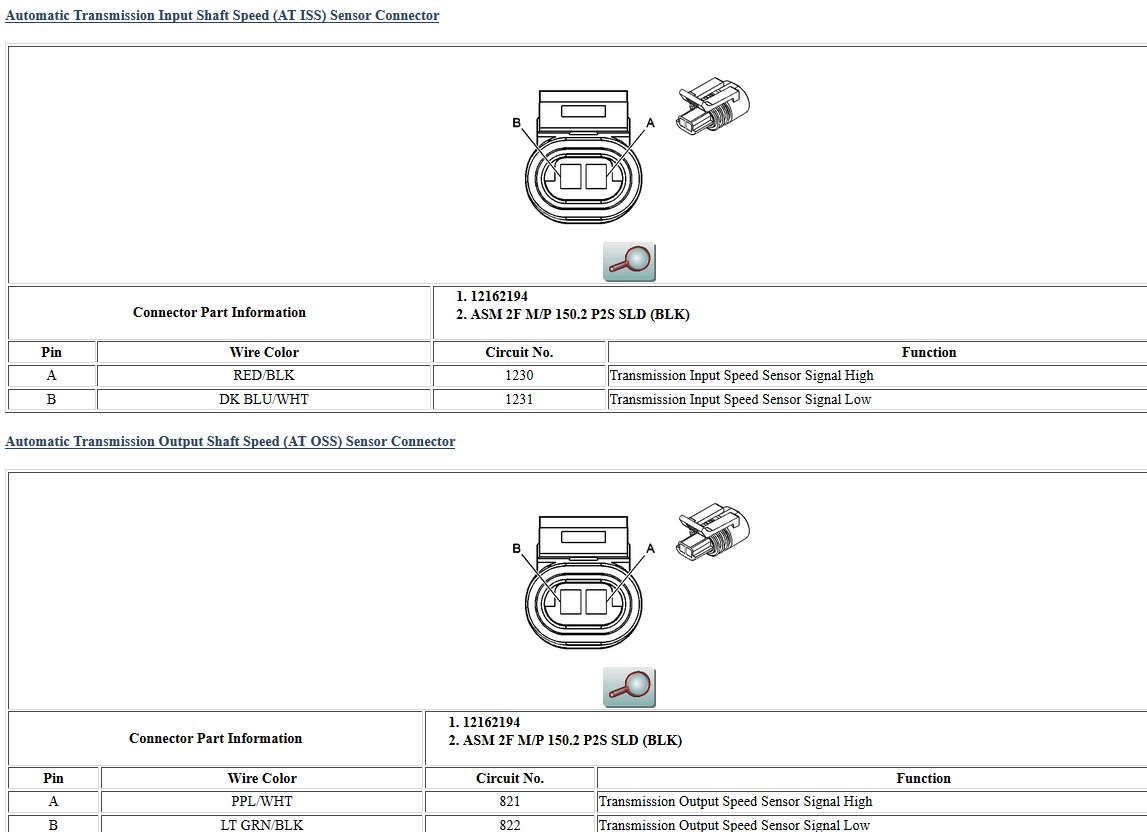
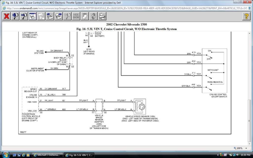
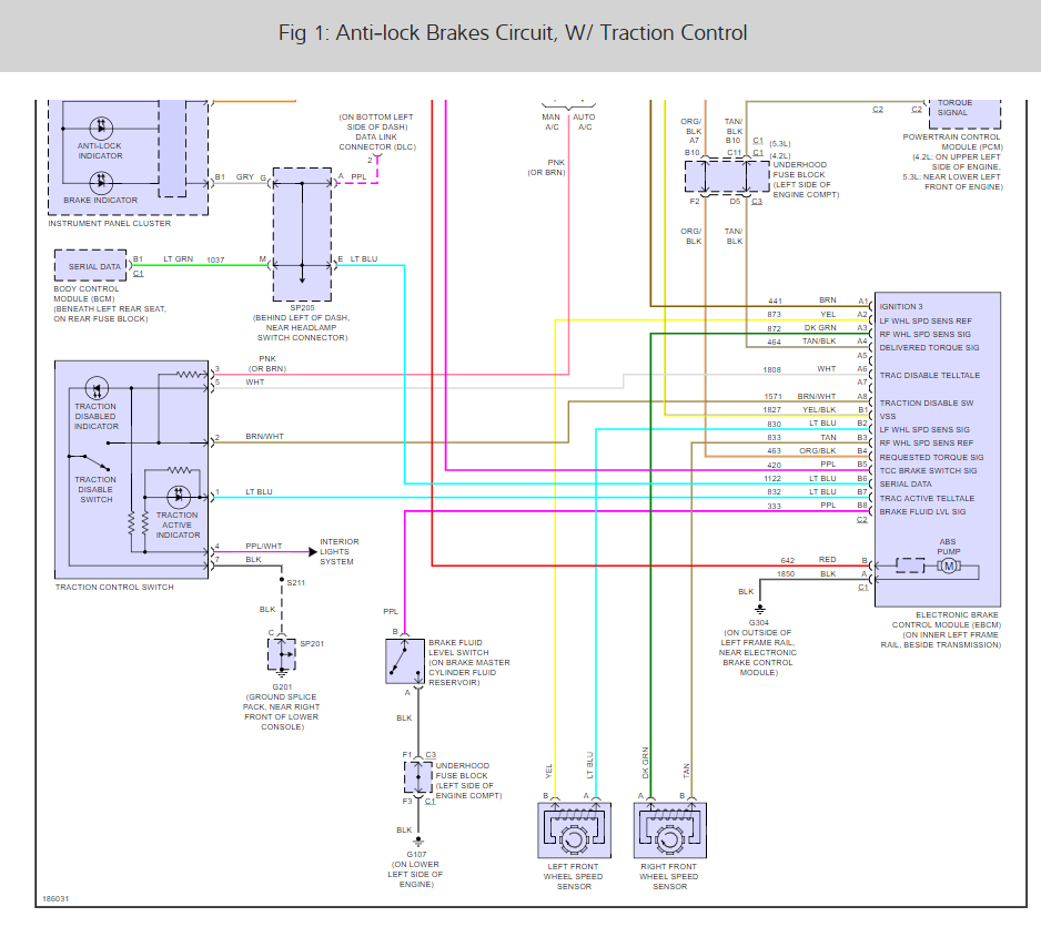
Gm vss wiring diagram. connector and vehicle speed sensor connector. These are only two connections needed for both 4L60E (65E) or a 4L80E (85E) transmissions. This system does NOT require the use of the input shaft speed sensors on the 4L65E or the 4L80E/85E transmissions. See Figure 1 for the pin out of required connections. VSS Sensor Signal Voltage CircuitAmazon Printed-Books & Kindle:http://www.amazon.com/s/ref=nb_sb_noss_1?url=search-alias%3Dstripbooks&field-keywords=mandy+co... PSI sells Standalone Wiring Harnesses for GM Gen II, III, IV, & V LS/LT based engines and transmissions. These harnesses include the Gen II LT1/LT4, Gen III (24x) LS1/LS6 and Vortec Truck Engines as well as Gen IV (58x) LS2, LS3, LS7, & … The VSS vehicle speed sensor is in the same basic location on a 4L60E 2wd, on the tail housing. The 95 is a different sensor than 96 and later, but the internal reluctor is the same. You will need to study the original wiring diagram for the vehicle and the donor vehicle. Could be as simple as snip-snip and splice (using waterproof butt splices ...
typical and abbreviated wiring diagram as well as how to set up your speedometer, tachometer, and fuel sensor. A detailed description of all the wiring and connections can be found in the full instruction manual. Install the supplied oil pressure, coolant temperature and speed senders. (see sensor pack manual) Mount and wire the control box. Hello - I am trying to install a VSS in my 80 Volvo which has a 97 S10 4.3 in it. The car has a 700r4 in it and when the conversion was done a VSS was never installed. I am now adding one, but it takes a special one because the speedometer is cable driven, but the VSS is used in the place where... The GM style pulse signal generator (part #SN16) is shown below in Figure B. ... If your transmission has a built-in electric vehicle speed sensor (VSS) or computer (ECM), a speedometer signal interface is required, shown below in Figure C. Red Black ... See Figure D below for a SN76 wiring diagram. Yellow Black White Red From ECM Tach Signal ... May 04, 2020 · Door Locks - 5 Wire Alternating 12 Volts Positive (Type C) Relay Wiring Diagram: The switch, when moved in either direction, applies both power and ground directly to motor legs without the use of any relays. Except, at the …
Disclaimer: * All information on this site ( the12volt.com ) is provided "as is" without any warranty of any kind, either expressed or implied, including but not limited to fitness for a particular use. Any user assumes the entire risk as to the accuracy and use of this information. Please verify all wire colors and diagrams before applying any information. T56 VSS Vehicle Speed Sensor Connector Wiring Pigtail LT1 LS1 Details New VSS Connector pigtail for GM T56 Transmissions including LT1 and LS1 Applications. Although I wasn't getting a correct VSS signal from the PCM, I was able to "adjust" the signal (through the DD VHX menu) to get the correct speed reading on my speedometer. 1992 Camaro 5 Speed Vss Wiring Diagram. Because of the importance of the vehicle speed sensor, we cannot recommend . On the left is the 4-pulse VSS used on manual transmission Camaros with TPI (or Camaro V6) and LT1 engine with a. Vehicle Speed Sensor Connector (Manual Trans Output Sensor) TPI, TBI, to be used with a T5 Conversion. Nov 28, 2021 · Conversions & Hybrids - Solution: Swap with 3 wire VSS - This is not a question, I'm putting this up in the hopes that it may help someone at some point. Most people swap in a GM transmission with their LS. In that case it's usually pretty easy to configure the GM PCM to drive the vehicle speedometer. My swap was into...
How to replace speed sensor 1994 k1500 suburban
First: The existing VSS cabling from my 99 Tahoe has a shielded two conductor cable for the one VSS and the drain wire is connected to the common ground. To add a second VSS for the 4L80 it seems that a second VSS is added, however commonly done with twisted pair, rather than shielded. The function of each is very different.

Repair Guides
4l60e wiring diagram – You will need a comprehensive, expert, and easy to understand Wiring Diagram. With such an illustrative guide, you will be capable of troubleshoot, stop, and total your projects without difficulty. Not merely will it assist you to attain your desired final results more quickly, but additionally make the entire method easier for everyone.

Gm Vss Wiring Diagrams | schematic and wiring diagram
Software Update: 250-8450/250-8451 General Motors Multi-Camera Video Interface (Updated 2/9/2017). This update adds the ability to select Blind Spot Cameras when moving as well as addresses a bug when the rear camera power was wired incorrectly.

T56 Wiring Diagram
GM VSS OSS 4L60E 4L60 R4 Vehicle Speed Sensor Brand New. $ Mar 24, · The new speed sensor plug will hook to the INPUT speed sensor, located abover the shifter shaft on the side of the 4L80E. That will complete the wiring changes at the transmission end. Now, you will need to go to the PCM connectors, and re-purpose the WHITE and TAN/BLACK ...

1991 k5 454 swap no speedometer - Blazer Forum - Chevy ...
Gm Vss Wiring Diagrams A wiring diagram usually gives counsel virtually the relative slant and concord of devices and terminals upon the devices, to help in building or servicing the device. This is unlike a schematic diagram, where the covenant of the components’ interconnections upon the diagram usually does not be consistent with to the ...
4L60E to 4L80E Wiring Swap - Page 16 - PerformanceTrucks ...

1992 Camaro 5 Speed Vss Wiring Diagram
Speed Sensor Wiring Diagram
ALFA Rally Computers - Small Systems Specialists

Chevy Cruze Maf Iat Sensor Wiring Diagram | schematic and ...

I have a 1994 chevy 1500 with a 5.7 motor and i was going ...

Speedometer is not working on a 91 camaro v6 3.1. Already ...
2004 Chevrolet Silverado 2500hd Input Turbine Sensor ...
![[DIAGRAM] Gm Vss Wiring Diagram FULL Version HD Quality ...](https://diagramweb.net/img/s10-vss-wiring-diagram-3.jpg)
[DIAGRAM] Gm Vss Wiring Diagram FULL Version HD Quality ...

1990 Chevy 700r4 Transmission Electronic Speedometer ...
1992 Camaro 5 Speed Vss Wiring Diagram

Speedometer not working. 1993 Chevy K1500 5.7. And ...

input/turbine speed sensor - GM Forum - Buick, Cadillac ...
ABS System Wiring Please?: Where Is My Rear Wheel Speed ...
![[DF_8824] Egr Valve Location In Addition Ford Oil Pressure ...](https://static-assets.imageservice.cloud/10866/89-gm-vss-wiring-diagram-wiring-diagram.jpg)
[DF_8824] Egr Valve Location In Addition Ford Oil Pressure ...

4l60e Speed Sensor Wiring

2001 Chevrolet Malibu 3.1L FI OHV 6cyl | Repair Guides ...

700r4 Transmission Speed Sensor Wiring Diagram
29 3 Wire Speed Sensor Diagram - Wiring Database 2020

VSS Vehicle Speed Sensor Connector Wiring Harness Plug GM ...

Chevy Truck: 1990 Chevy 1500 Vss Wiring Diagram

1992 Camaro 5 Speed Vss Wiring Diagram
Help 92 RS Speedo dead - Third Generation F-Body Message ...

96 Chevy 1500 Wiring Diagram - Wiring Diagram Networks

2002 trailblazer VSS. where is it located, and is the ...
wiring diagram for chevy drac - Wiring Diagram

1990 Chevy 1500 Wiring Diagram For Speed Sensor - Wiring ...

Electronic Speedometer how to and why from NVU - New ...
Wiring Help - VSS plug details - LS1TECH - Camaro and ...

94 Chevy Truck Wiring Diagram - Wiring Diagram Networks

Repair Guides

| Repair Guides | Automatic Transmission (2000) | Dtc ...

T56 VSS Speed Sensor Connector Wiring Pigtail GM LT1 LS1 ...
Wiring Diagram For 1990 Gmc G3500 Trac Vss

Gm Vss Wiring Diagrams | schematic and wiring diagram


Comments
Post a Comment