38 time clock wiring diagram
Dimension: 645 x 471. DOWNLOAD. Wiring Diagram Images Detail: Name: paragon 8141 00 wiring diagram - Paragon Timer Wiring Diagram Diagrams Schematics Throughout Defrost Time Clock 0. File Type: JPG. Source: natebird.me. Size: 193.58 KB. Dimension: 1659 x 891. Page 6 of 16 November 2016 ProxPro Wiegand/Clock-and-Data Installation Guide, 5355A-900, Rev. N.3 3 Wiring 3.1 Standard Wire Connections TB1
The X terminal would be for.tork time clock wiring diagram - A Novice s Guide to Circuit Diagrams. Not sure how to wire my Tork 1103 timer. An initial take a look at a circuit representation may be confusing, yet if you can read a subway map, you could review schematics. In the wiring diagram above, it shows white neutral wire running to Tork ...

Time clock wiring diagram
http://www.sparkyuonline.com In this video i show how to wire a 110 volt time clock that will operate a contactor. The contactor handles the electrical vol... Deep Cover said: Take the power feeding the time clock to the switch. Then take the switch leg at the time clock to the switch. This will put the switch leg on the time clock and the switch. Click to expand... Exactly. Make sure you use the same circuit to feed the switch as the time clock. Find solutions to your paragon defrost timer 20 wiring diagram question. Get free help, tips & support from top experts on paragon defrost timer Adjustable Defrost Cycle Duration: 4 to minutes in S and Paragon Wiring Diagrams Electric Heat Defrosting S & S Series. how to test paragon 20 defrost timer rh waterheatertimer org Paragon 20 Wiring Schematic Paragon Time Clock tors, Paragon ...
Time clock wiring diagram. Troubleshooting: Clock Time ... Wiring for the internal relay closure: Maximum Voltage: 60vdc, 125vac Maximum Switched Current: 1A Maximum Carrying Current: 1A Specifications 1 2 3 oon oall los oall on tiat + - ALARM SYSTEM o Relay Connection Diagram 1 3 Connector Relay RELAY. 8 American Time PoE Installation Manual 1 3 5 7 9 11 2 4 6 8 10 12 ... WIRING. DIAGRAM. V 2 WIRE. AND GROUND. LR UL and align the exact time-of-day on the CLOCK-DIAL (the time now, when. WIRING INSTRUCTIONS: To wire switch follow diagram above. Use solid or of CLOCK-DIAL, pointing to time (AM or PM) when ON and. OFF operations are. Connect the ground wire to the green screw located on the Intermatic timer mechanism. The hive instructions highlight the single channel receiver wiring diagram below. Hive heating wiring diagram.Diagram S Plan Plus Wiring Diagram Full Version Hd Quality Wiring Diagram Diagramland Andreapendibene It. Wiring hive smart thermostat to combi boiler diynot forums dual reciever tz uk for a logic 30 with installation vaillant ecotec plus 824 als web page new relay home question ... Lighting Time Clock Wiring Diagram - One of the most difficult automotive repair tasks that a mechanic or fix shop can allow is the wiring, or rewiring of a car's electrical system.The pain in point of fact is that all car is different. subsequently irritating to remove, replace or repair the wiring in an automobile, having an accurate and detailed lighting time clock wiring diagram is ...
2 Aerian ie AllSync Master Installation & Operation Manual American Time 140 3rd Street South, PO Box 707 Dassel, MN 55325-0707 Phone: 800-328-8996 Fax: 800-789-1882 american-time.com IBM (International Time Recording Co.) Master Clock Wiring. Hello. I purchased a large International Time Recording Co. master clock on ebay a couple of weeks ago. Perhaps some of you saw it. It's one of those big ones installed in a school in 1927 to run the slave clocks and the bell system. Its model number is 13 6 12. Wiring diagram - volt free switching. The dia- gram above shows wiring for a potential-free load. ... head on the clock face aligns with the correct time.2 pages clock motor: 208-277 volts - 60 hz. clock motor voltage and cycle must be as specified. to order replacement, indicate part no. (wg--) on motor cover. wiring diagram 240 v 2 wire and ground lr3730 document1 10/30/03 1:36 pm page 1
Size: 637.36 KB. Dimension: 1632 x 1200. DOWNLOAD. Wiring Diagram Images Detail: Name: tork time clock wiring diagram - Gallery Intermatic Pool Timer Wiring Diagram Best Wiring A tork‚ Dtu40 for 240 Volts Youtube. File Type: JPG. Source: sanantonioroselive.com. Size: 582.33 KB. Dimension: 1920 x 1080. They want these to be controlled by a time clock an photo cell but also run through a key switch and contactor. It's been some time since I wired contactors and was just looking for some advice on it or if someone could provide a wiring diagram I would be very grateful Thanks in advance . Reply to Sean burge. D. Des 56-Esteemed. Arms ... On delay timer circuit diagram wiring diagram contactor with push button circuit diagram of delay timer on off power off delay timer circuit diagram 2 way lighting circuit triggering transformer push button fan switch light activated switch circuit diagram wd081 text. Each component should be placed and linked to other parts in particular manner. Remove timer mechanism by releasing spring clip on bottom. ... Wire in accordance with National and Local Codes (see wiring diagrams).4 pages

Wiring a contactor with an mcb and rccd - D.I.Y. Kit - UK420
Fix backplate to socket box. 4. Connect wiring in accordance with wiring diagram. Do not combine solid and flexible conductors in the same terminal.4 pages
ICS Time Delay Module Applications and Wiring
Sangamo Time Switch, please read these instructions carefully. ... load as in wiring diagrams above. ... See 'Setting Standard 24 Hour Clock'.2 pages
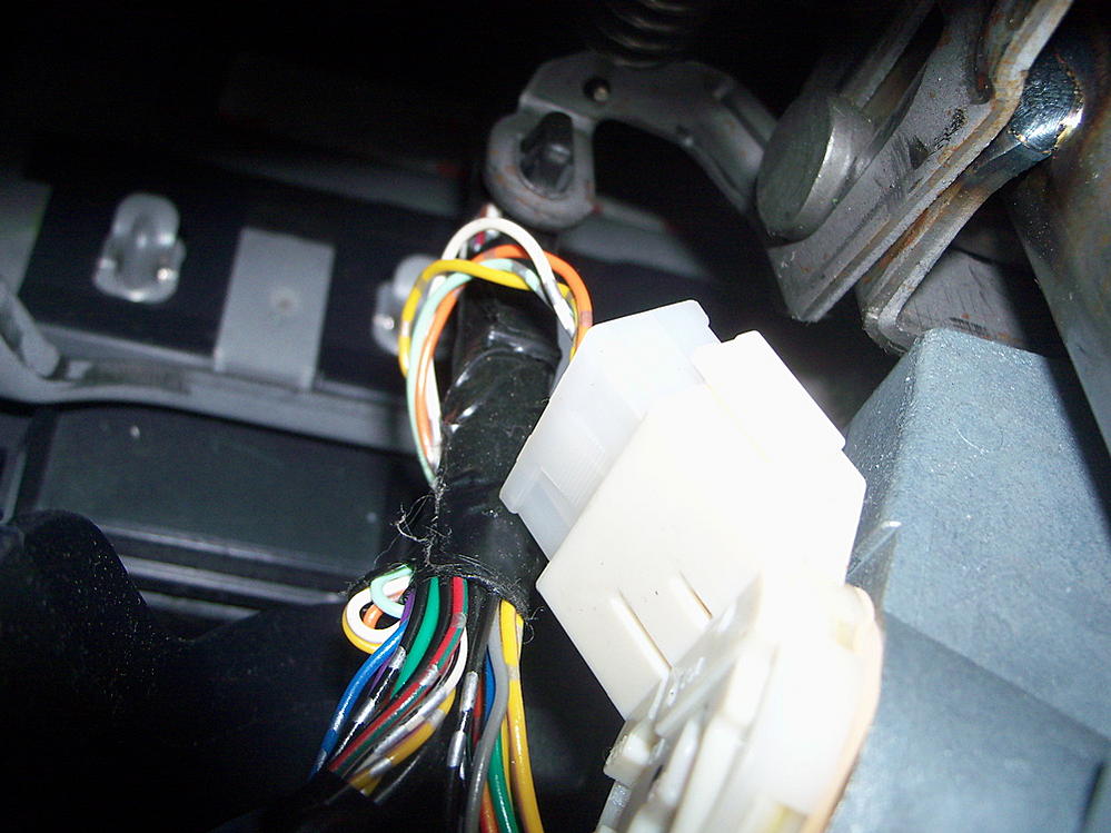
Turbo Timer Wiring Question - EvolutionM - Mitsubishi Lancer ...
Photocell And Timeclock Wiring Diagram. Photocells and timers are switches that turn on and off automatically. Photocells are A time clock has a built-in clock. Photocell and Timer Wiring Diagram 1. So when the photocell turns on, it disconnects the time clock output and Here is the schematic for your application, minus the power.
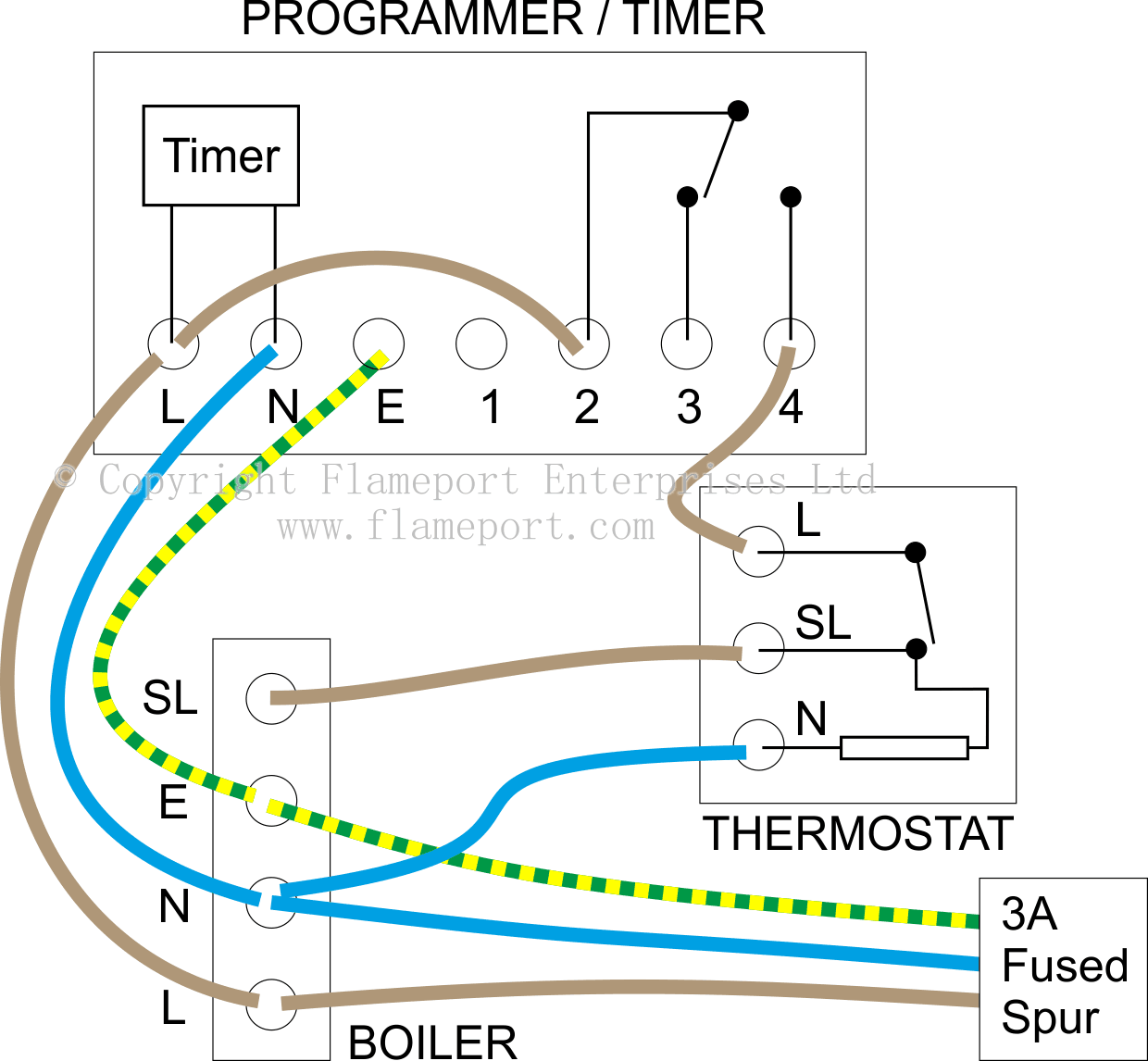
External programmers for combination boilers
Bells may be arranged either on 110 volt current or on the storage battery voltage used by the master clock system. Jeffrey R. Wood. Wiring diagram for a SETco Clock System installed at the Southampton, New York High School in 1923/24. The High School became the Southampton Town Hall in 1970 and the clock must have been removed about that time.

Photocells & Timers - Electrical 101
Put the time clock contacts AFTER the photocontrol in series with the red lead. Set the time clock to come on during daylight and off at 3AM. Photocontrols need to be hot all the time. In operation, photocontrol turns on the lights at dusk (time clock is already on) then the time clock turns them off at 3AM. -Hal

Schneider 24H Timer Switch With Reserve
In analog clocks, the minute pulse also is the power supply. Before initiation, all slave clocks must be manually pre-set to indi- cate the starting time. All ...1 page

Timer Testing Wiring Diagram | Timer | Timer Wiring | Timer switch| By Tech Bondhon
Dec 16, 2008. #3. no diagram, but we used to do a pretty simple wiring set up. Feed the photocell and clock motor with "Line" (and neutral) (this often entails taking the motor lead off the contcat terminal) Run the "load" of the photocell thru the clock contacts. and feed the contcator/light. In this manner, the clock motor runs all the time.

Wiring diagram to use Timer Relay for Siren Operation | Tech ...
TYPICAL WIRING DIAGRAM CLOCK MOTOR / VOLT 3 WIRE SUPPLY TO LOADS GROUND LINE 2 LINE 1 A 2 4 GR. 1 3 NEUT. The T Series Mechanical Time Switch has proven it can stand the test of time. These dependable time switches can handle electrical loads up to 40 A per .

Timer Testing Wiring Diagram | Earth Bondhon | Timer, Digital ...
Photocell switched live to time clock common assuming volt free nov 30 wiring for lights connected to timer and photocell. The black line wire connects to line voltage from the panel the red load wire connects to the light s the white neutral wire connects to the neutral wires of the circuit.
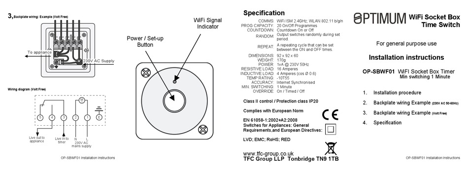
OPTIMUM OP-SBWF01 INSTALLATION INSTRUCTIONS Pdf Download ...
Has anyone got a wiring diagram for a external lighting circuit which has a photocell, time clock and a override switch! Thanks John in this thread in this sub-forum in the entire site

12V Relay With Timer Switch : 4 Steps - Instructables
CLOCK. TIMER DAY HOUR. MIN. P. ON. Mo. 1ON 13:44 56. Diagram 1 CSP Cable Planning ... The wiring diagrams show the wiring connections for the Door Entry.7 pages
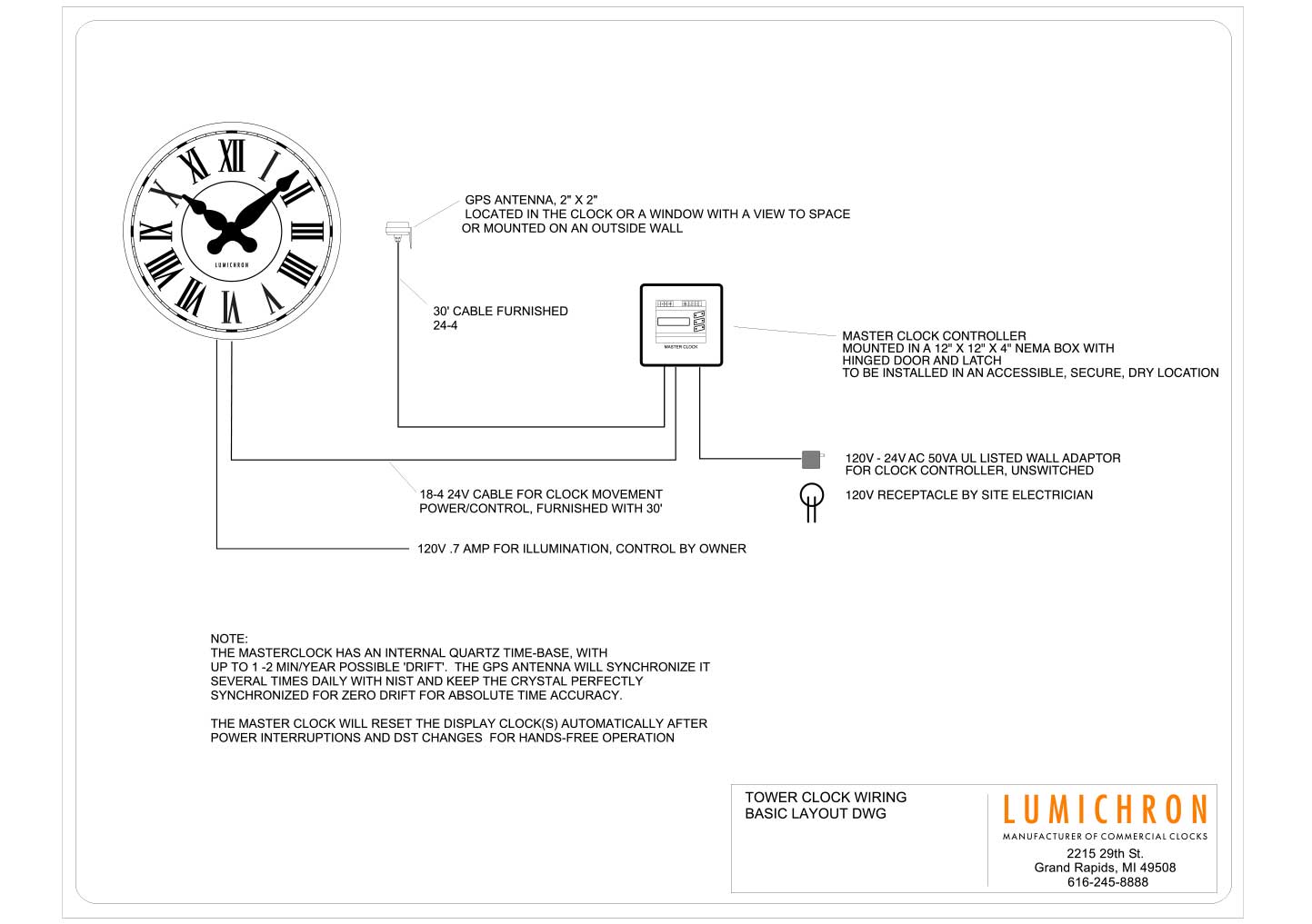
Wiring Diagram for a Tower Clock with a master clock and GPS ...
photocell wiring diagram - You'll need an extensive, professional, and easy to comprehend Wiring Diagram. With this sort of an illustrative manual, you will be able to troubleshoot, avoid, and complete your tasks with ease. Not merely will it assist you to achieve your required final results faster, but in addition make the whole procedure easier for everybody.
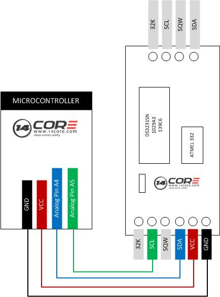
Wiring the DS3231 IIC Precision Real Time Clock Module ...
These dependable time switches can handle electrical loads up to 40 A per . WIRING DIAGRAM WARNING Risk of Fire or Electric Shock • Disconnect power at the circuit breaker (s) or disconnect switch (es) before installing or servicing. • Installation and/or wiring must be in accordance with national and local electrical code requirements.
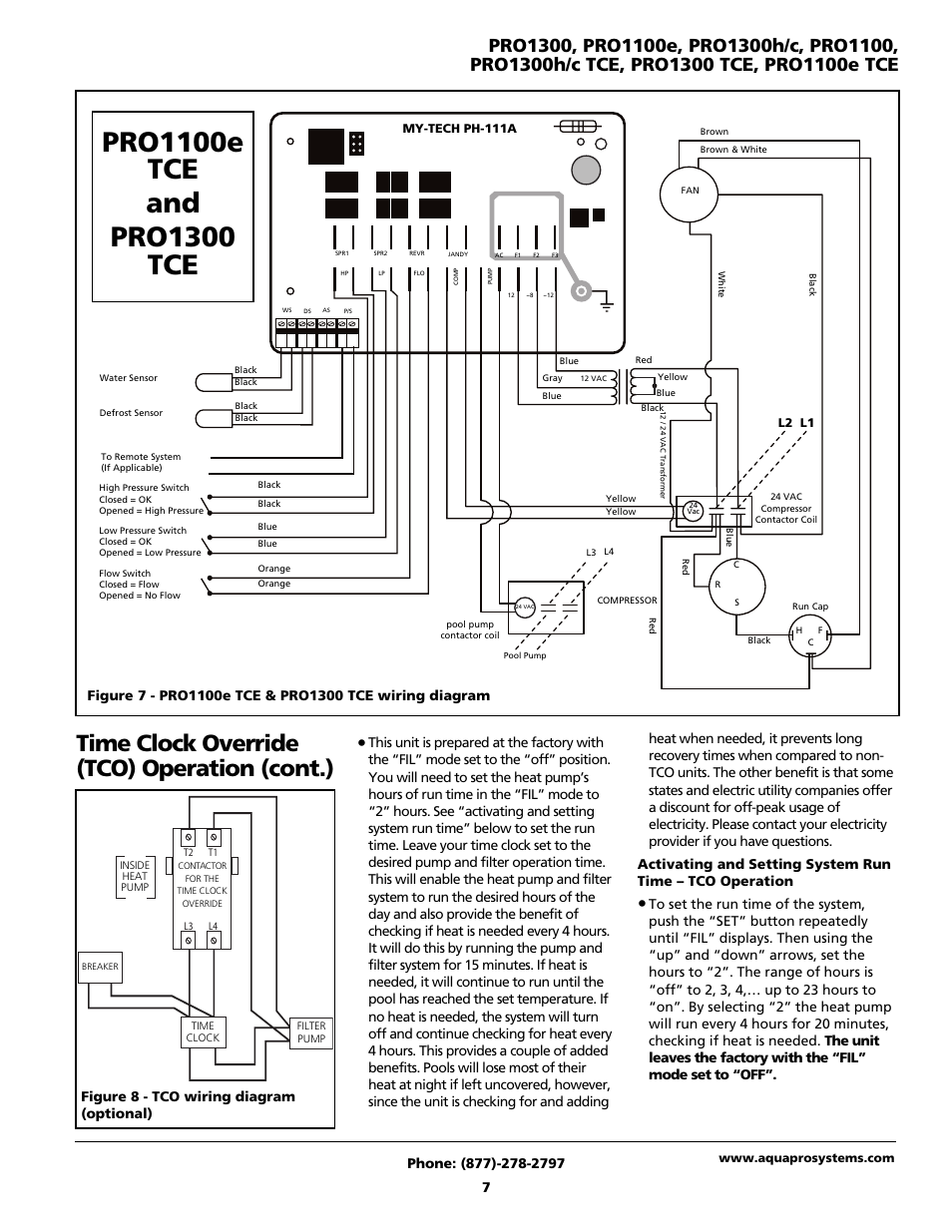
Time clock override (tco) operation (cont.), Figure 8 - tco ...
Find solutions to your paragon defrost timer 20 wiring diagram question. Get free help, tips & support from top experts on paragon defrost timer Adjustable Defrost Cycle Duration: 4 to minutes in S and Paragon Wiring Diagrams Electric Heat Defrosting S & S Series. how to test paragon 20 defrost timer rh waterheatertimer org Paragon 20 Wiring Schematic Paragon Time Clock tors, Paragon ...

Wiring diagram for timer and tether. | Download Scientific ...
Deep Cover said: Take the power feeding the time clock to the switch. Then take the switch leg at the time clock to the switch. This will put the switch leg on the time clock and the switch. Click to expand... Exactly. Make sure you use the same circuit to feed the switch as the time clock.

NEED WIRING DIAGRAM FOR INTERMATIC T1975 - Fixya
http://www.sparkyuonline.com In this video i show how to wire a 110 volt time clock that will operate a contactor. The contactor handles the electrical vol...
![View 43+] Washing Machine Timer Switch Wiring Diagram](https://ae01.alicdn.com/kf/HTB1KuOpRXXXXXaZaXXXq6xXFXXXF.jpg?size=42487&height=511&width=531&hash=141f9bf3b062436292ddb246281010dd)
View 43+] Washing Machine Timer Switch Wiring Diagram
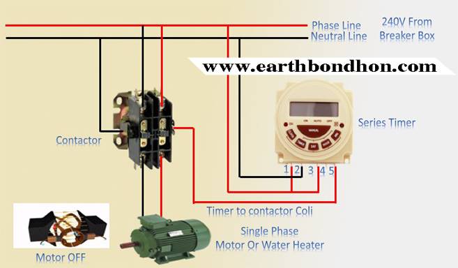
PB Series Timer Wiring To Motor Control – Earth Bondhon

staircase timer wiring diagram Manufacturers and Suppliers ...

Primax Channel - washing machine timer wiring diagram 7 ...

H3CR Timer: Wiring Power Supply and Input Devices | FAQ ...

INTERMATIC FM/1 SERIES OPERATING INSTRUCTIONS Pdf Download ...
Wiring the MAX6958/59 to 4-Digit Clock Displays
How to Install an Analog Time Switch: A Simple Guide for ...

DEFROST TIMER CONNECTION! REFRIGERATOR TIMER CONNECTION! DOUBLE DOOR REFRIGERATOR TIMER CONNECTION

8 pin timer relay wiring diagram - electrical and electronics ...
8 Pin Timer Relay Wiring Diagram | Basic Timer Connection And Function |

How to wire twin timer
How to Install BLITZ Turbo Timer (With Pictures)
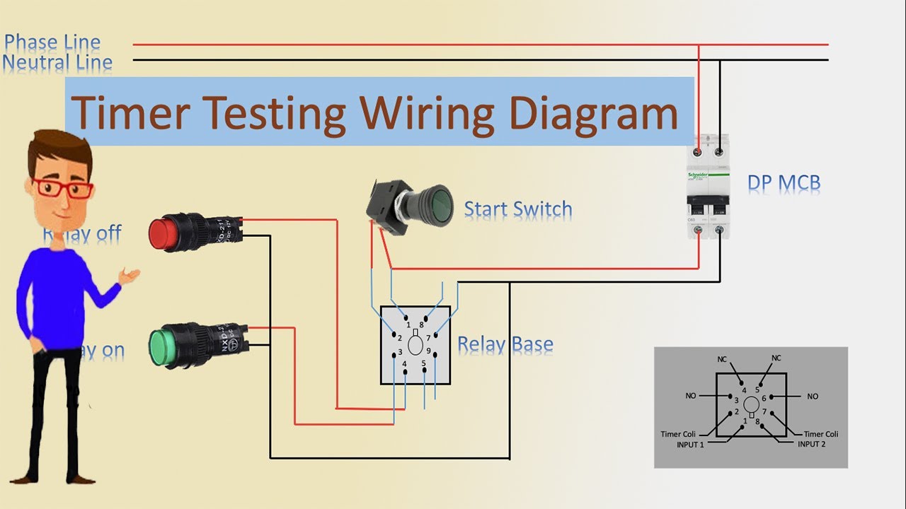
Timer Testing Wiring Diagram | Timer | Timer Wiring | Timer Wiring

Soldering Iron Temperature Control PLC Cycle Timer Circuit ...

Refrigerator defrost timer wiring diagram

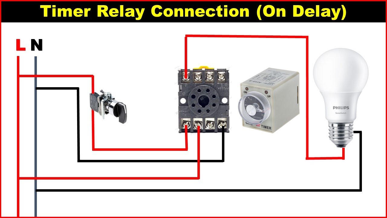
A diagram about how on delay timer works, or star delta timer ...

H3CR Timer: Wiring Power Supply and Input Devices | FAQ ...
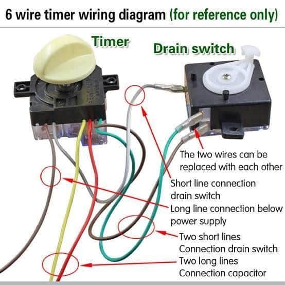
Electrical & Mechanical Info - 6 Wire timer Wiring Diagram ...

How to wire Intermatic T104 and T103 and T101 timers

How to wire twin timer

Digital Timer Control Switch Connection and Working


Comments
Post a Comment