38 air brake chamber diagram
This video gives a detailed overview of the various components of service chambers and spring brakes. We identify long stroke, standard stoke, and different ... (v) Brake chamber. Brake chamber is used to transfer the force of compressed air to mechanical linkages. Service-brake chambers convert compressed air pressure energy into mechanical force and movement, which apply the vehicle’s brakes. A brake chamber is a circular container divided in the middle by a flexible diaphragm.
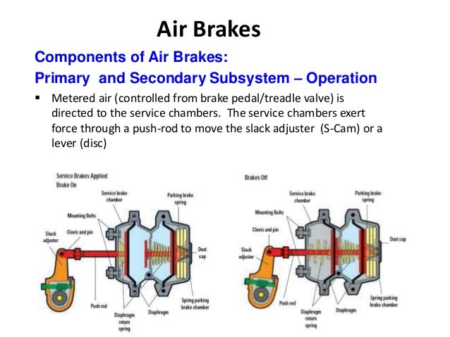
Charging: The system must be pressurized with air before the brakes will release.At rest, the brakes remain engaged. Once the system reaches its operating pressure, the brakes are freed and ready to use. Applying: As the brakes are applied, air pressure decreases.As the amount of air decreases, the valve allows air back into the reservoir tanks, while the brakes move to the applied position.

Air brake chamber diagram
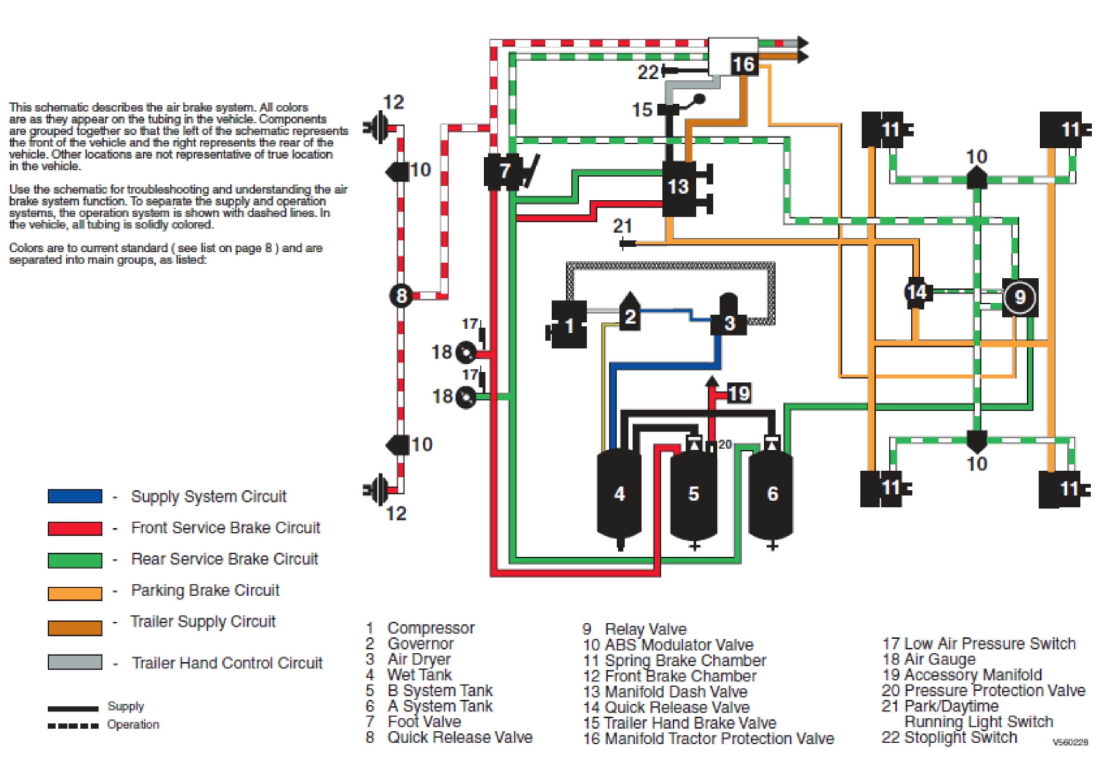
The purpose of an air brake system on heavy duty vehicles is to convert air pressure to mechanical energy to activate the foundation brakes. Federal Motor Vehicle Safety Standard 121 dictates how this is to be done for over-the-road vehicles. The purpose of this book is to help you construct Meritor WABCO Truck and Tractor air systems. -Brake drum out of round.-Brake chamber diaphragm failure.-Wrong brake lining.-Broken slack adjuster or foundation brake parts. 8.) Air Pressure Will Not Rise To Normal-Faulty air gauge (registering incorrectly).-Excessive valve or fitting leakage.-Governor out of adjustment.-Slipping compressor drive belt.-Faulty compressor.-Broken supply line ... Air Brake Systems" or FMVSS 121. This booklet will cover the most common air brake system designs from 1975 to 2006. Air Compressor and Air System Pressure - You should be aware of common air pressure thresholds of your motorcoach's brake system. The air pressure gauge tells you the adequacy of the air system.
Air brake chamber diagram. Description 8 SAAP-CABCP03A2TLET 3 OFAAS BRAKE CHAMBER COMPONENTS (con't) SAP30241L Release Stud Assembly Type 30 For 2424L & 3030L SAP30242L Clevis Assembly with Pin Type 24 & 30 For 1024L, The diagram shows the brakes in the applied position. The S-cam is rotated so the high points have acted against the cam rollers and forced the brake shoes against the drum. When the brakes are released, the brake cam shaft returns the brake cam to the normal position. The Haldex Aftermarket Quick Reference Catalog Actuators l Air Disc Brakes l Air Treatment/Airline l Air Valves Anti-Lock Brake Systems (ABS) l Brake Adjusters Clutches l Compressors l Electrical l Friction Remanufactured Products l Suspension Valves l Water Pumps Quality parts for vehicles at any life stage.
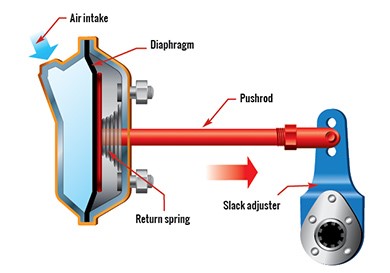
Piping Diagram Page 6 Wiring Diagrams Page 6 Warning lamp and Page 8 ... Spring Brake Chamber) 7 Drain valve 8 Load Sensing valve - pneumatic 9 Test point 10 MCER Valve. ... 9 8 9 10 9 14 9 13 11 11 11 11 11 11 PIPING DIAGRAM - 2 Line Air Brake system, 3 Axle Semi-Trailer, Spring Brakes, Air Suspension. Fig 5 6 WIRING DIAGRAM - ISO 3731 (24S ... emergency or parking brakes offered by some air brake system manufacturers in their spring brake control valves. This option guards against over-torque of the foundation brakes causing such problems as bent chamber push rods, broken camshafts, cracked drums, lining damage, damaged chamber brackets, etc. Below, is a diagram of a front brake air chamber, courtesy of GMC Truck Division. It has a single diaphragm which pushes the push rod to the right when air enters into the chamber from the air inlet. All of these brake chambers have sizing information. The larger the chamber size, the more force the chamber can generate. Section 15 - Brake Chambers and Components FPA No. Description Application Alternate No. Brake Chamber Wedge Brakes Type 12 CA2503 Brake Chamber Wedge Brakes 1212B-3.00 AN1212B-3.00R ... AIR BRAKE HOSES Diaphragm VH90 Vacuum Brake VH90-4 Hydropowers 885820R1 T Release Bolt Assy T16 - 30/30 Brake 11M011 Chambers FP1003015 Clevis Pin ITAL 33557V
3. Check brake chamber push rod travel (refer to chart below for the CVSA adjustment limit. With the parking brakes released and service brakes applied with 80 to 90 psi of air pressure to the service chambers. 4. Check the angle formed between the brake chamber push rod and the slack adjuster arm. the rear brake chambers. At the same time, air is also drawn from the secondary reservoir, passes through the foot valve and is passed on to the front brake chambers. If there is air loss in either circuit, the other will continue to operate independently. Below, is a diagram of a front brake air chamber, courtesy of GMC Truck Division. It has a single diaphragm which pushes the push rod to the right when air enters into the chamber from the air inlet. All of these brake chambers have sizing information. The larger the chamber size, the more force the chamber can generate. AIR DISC BRAKES PARTS LIST 5 L1063 Rev G AIR DISC BRAKE CALIPER ATTACHMENT HARDWARE KIT PART NO. DESCRIPTION CONTAINS QUANTITY PER AXLE S-33649-5 MAXX22T Caliper to Torque Plate Bolt Kit 12 Bolts and 12 Washers 1 S-33649-6 MAXX22T Caliper to Torque Plate Bolt Kit 6 Bolts and 6 Washers 2 AIR CHAMBER PART NO. DESCRIPTION CONTAINS QUANTITY PER AXLE

Airline Brakes Chamber
Typical 6 Wheel Air Brake System. These diagrams are provided for basic identification only. Always consult a professional technician to properly troubleshoot your system. Typical 10 Wheel Brake System. These diagrams are provided for basic identification only. Always consult a professional technician to properly troubleshoot your system.
What do air brakes use to make the brakes work? - Quora
brake chambers and applies force to the push rod, transferring the force to the SCam or air disc brake. (See page 19 for more about foundation brakes.) Frictional forces slow the wheels and the vehicle comes to a stop. When the brakes are released, the air in the brake chambers is able to be quickly rel eased and enable the vehicle to drive away.
Type 3030 Brake Chamber Assembly
50 GOLD SEAL SPRING BRAKE CHAMBERS PART No. D ESCRIPTION GC2430 Type 24/30, Less Clevis GC3030 Type 30/30, Less Clevis GC2424 Type 24/24, Complete With Clevis GC3036 Complete Chamber Type 30/36, Less Clevis GC3636 Complete Chamber Type 36/36, Less Clevis SPRING BRAKES SEALED PIGGYBACK CHAMBERS PART No. D ESCRIPTION GP3036 TYPE 30/36 GP Gold Seal Piggyback GP3636 TYPE 36/36 GP Gold Seal Piggyback
Trucks: How does an air brake work? - Quora
tegrity of the air brake system. Motor Vehicle Safety Standards (MVSS) 121 requires an air capacity 12 times the total vol-ume of all air brake chambers on the vehicle. For additional information on calculating total air volume and brake chamber rated air volumes, refer to Liftable Axle Air System Requirements section in this bulletin.

Unit 2: Air Brakes in Commercial Vehicles - KNILT
Setting the parking brakes releases the air from the spring brake chambers (see air brake chambers) which allows the powerful spring inside the spring brake chamber to push the slack adjuster which sets the spring brakes. This all happens while the service brake chamber is already pushing on the slack adjuster to set the service brake.

30/30 PIGGYBACK AIR BRAKE CHAMBER KIT - Walmart.com
The service brakes will operate with apply and release air in the service (control) line by the tractor hand control or foot control valve. HOW TO IDENTIFY YOUR SYSTEM All types of trailer air brake systems can be identified for troubleshooting purposes by starting from the brake chamber or spring brake assembly.

Article: The Brake System – Adding Spring Brakes – Flxible ...
Brake Chamber Tech Info Service Brake Chambers. The service brake chamber is used when only the application of service brake air is required on an axle. There will be no emergency braking provided on this axle. You will find service brake chambers on steer axles, some rear axles, and old trailers that use a relay emergency valve to apply parking air pressure to the service chamber.

Beautiful boundless planet/Fangruida
An air brake or, more formally, a compressed air brake system, is a type of frictionbrake for vehicles in which compressed air pressing on a piston is used to apply the pressure to the brake pad needed to stop the vehicle. We are supplying kinds of Air Brake Chamber Types with different size. Types: Single Room Air Brake Chamber & Double Room ...

S-cam Air Brakes - YouTube
With the introduction of spring brakes, anti-compounding and 121 air brake systems, because a valve is leaking air out of its exhaust, does not mean the valve is at fault. If a spring brake is leaking from the the spring brake to the service brake side, that air will travel back up the service line and out the exhaust of the next valve back.

Article: The Brake System - An Airbrake Primer - Flxible ...
hydraulically or with air. Air brakes are similar in some ways to hydraulic brakes except that compressed air is used to actuate the brakes instead of brake fluid. The potential energy of an air brake system is from compressed air. The force delivered to the wheels has nothing to do with the pressure applied to the brake pedal.

Canal Engineering, The Falkirk Wheel, Falkirk, Stirlingshire, Scotland.
Standard Clamp Type Brake Chamber Type Adjustment Limit Type Adjustment Limit 9 1-3/8" 24 1-3/4" 12 1-3/8" 30 2" 16 1-3/4" 36 2-1/4" 20 1-3/4" DD-3 2-1/4” NOTE: Long stroke chambers are identified with square air ports or port bosses and special trapezoid ID tags. Long Stroke Type Brake Chamber Type Adjustment Limit Type Adjustment Limit
Brake Chamber Diagram | My Wiring DIagram
Air Brake Systems" or FMVSS 121. This booklet will cover the most common air brake system designs from 1975 to 2006. Air Compressor and Air System Pressure - You should be aware of common air pressure thresholds of your motorcoach's brake system. The air pressure gauge tells you the adequacy of the air system.

Tractor Trailer Air Brake System Diagram — UNTPIKAPPS
-Brake drum out of round.-Brake chamber diaphragm failure.-Wrong brake lining.-Broken slack adjuster or foundation brake parts. 8.) Air Pressure Will Not Rise To Normal-Faulty air gauge (registering incorrectly).-Excessive valve or fitting leakage.-Governor out of adjustment.-Slipping compressor drive belt.-Faulty compressor.-Broken supply line ...

Sky
The purpose of an air brake system on heavy duty vehicles is to convert air pressure to mechanical energy to activate the foundation brakes. Federal Motor Vehicle Safety Standard 121 dictates how this is to be done for over-the-road vehicles. The purpose of this book is to help you construct Meritor WABCO Truck and Tractor air systems.
brake chamber stroke chart - Conomo.helpapp.co

Image from page 637 of "Cyclopedia of locomotive engineering, with examination questions and answers; a practical manual on the construction care and management of modern locomotives" (1916)

Image from page 111 of "Railway mechanical engineer" (1916)
Jak nie holować pojazdu - Wykop.pl

Image from page 208 of "Air brakes, an up-to-date treatise on the Westinghouse air brake as designed for passenger and freight service and for electric cars" (1918)

The Official Air Brake Handbook

Patent US20130075212 - Parking Brake Chamber Internal ...

Mechanical Subsystem of a S-cam Air Brake System [7 ...
Brake Chamber Diagram | My Wiring DIagram
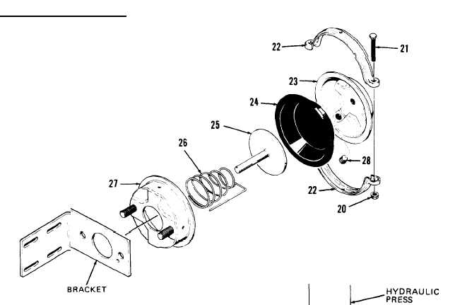
DISASSEMBLY OF AIR CHAMBER

The S-cam foundation brake | Download Scientific Diagram

19181203 - GM Chamber. CHAMBERRR, MGM, CHMBRJUZ ...

15259391 - GM Connector. CONNECTORFRT, CHAMBER | Wholesale ...

Image from page 770 of "Cyclopedia of locomotive engineering, with examination questions and answers; a practical manual on the construction care and management of modern locomotives" (1916)
School bus air brake chamber : Justrolledintotheshop

Image from page 253 of "The 20th century toolsmith and steel worker; a complete, practical, and scientific book, written by a thorough expert mechanic and steelworker, especially in the interests of blacksmiths, toolsmiths, toolmakers, and all mechanics c
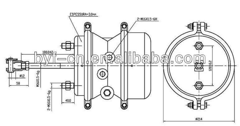
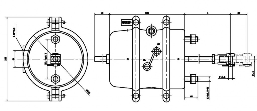
Byf Stroke 64mm Double Diaphragm Spring Brake Chamber ...

Figure 4-26. Fail-safe chamber assembly schematic diagmm ...
Types Of Air Brake Chamber Semi Trailer Air Brake System ...

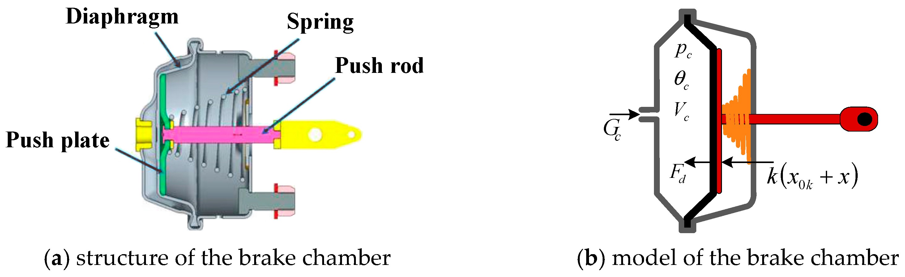
Brake chamber cross section & its Model | Download ...
Article: The Brake System - An Airbrake Primer - Flxible ...

Do You Know How To Use Air Break? - ProProfs Quiz

00646364 - Diaphragm. Air brakes & chambers | Wholesale GM ...

http://www.truckt.com Air Brake Chambers Explained


Comments
Post a Comment