39 ts diagram otto cycle
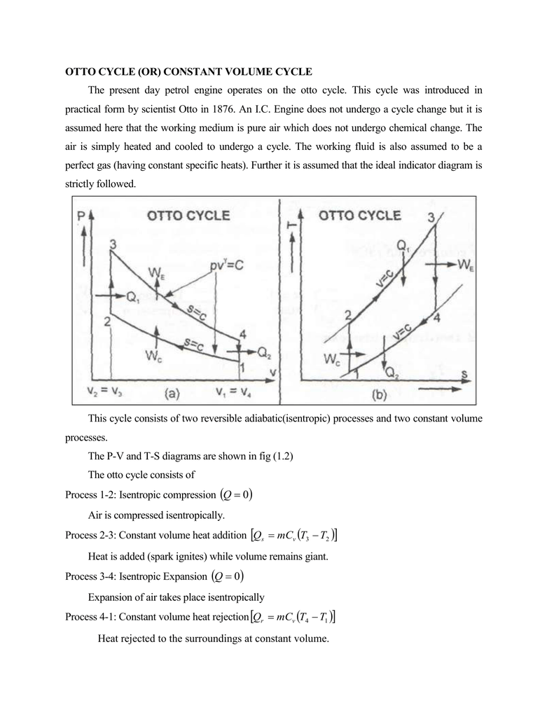
Pressure-Volume (p-v) Diagram of Four-stroke Otto cycle Engine. The ideal Otto cycle consists of two constant volume and two reversible adiabatic or isentropic processes as shown on PV and T-S diagrams. Let the engine cylinder contains m kg of air at point 1. At this point, let p1, T1, andV1 be the pressure, temperature and volume of air. To move an airplane through the air, thrust is generated by some kind of propulsion system. Beginning with the Wright brothers' first flight, many airplanes have used internal combustion engines to turn propellers to generate thrust. Today, most general aviation or private airplanes are powered ...
NPTEL provides E-learning through online Web and Video courses various streams.
Ts diagram otto cycle
May 1, 2019 - Otto cycle is a thermodynamic cycle upon which a spark ignition engine works. SI engine uses petrol fuel. Otto cycle was invented by Nicolas Otto in 1876. An air standard Otto-cycle model with heat resistance, heat leak and internal irreversibility coupled to two constant temperatures, one at hot reservoir T H and other at cold reservoir T is shown ... Fig.1 shows the limitation of the maximum cycle temperature due to heat leakage in the temperature-entropy diagram of an air standard Otto cycle model.
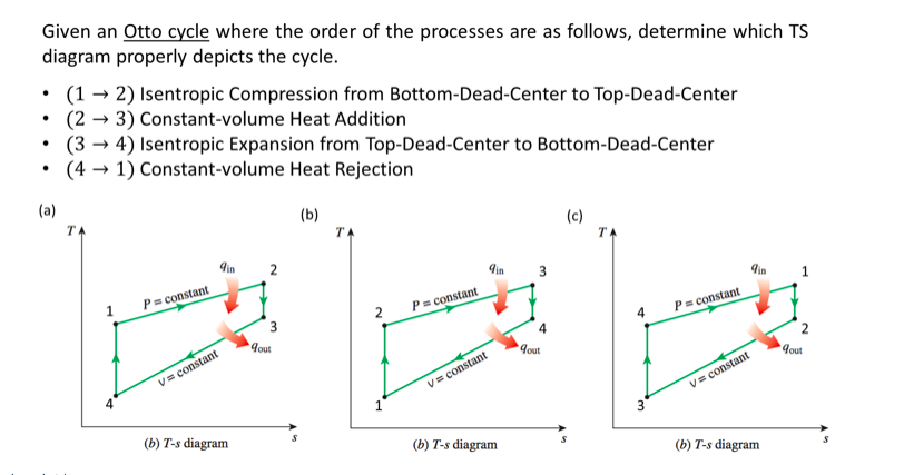
Ts diagram otto cycle. Otto Cycle is a constant volume cycle on which petrol and gas engines work. The Otto cycle consists of 4 processes and are as follows. Process 1-2: Reversible Adiabatic Compression or Isentropic Compression. Process 2-3: Constant Volume heat supply. Process 3-4: Reversible Adiabatic Expansion or Isentropic Expansion. Ask any question and get an answer from our subject experts in as little as 2 hours. Please watch: "Last minute important tips for GATE 2020 exam #gate2020 #gate" https://www.youtube.com/watch?v=nSjQbTFemWQ --~-- otto cycle - si engines full Hence, thermal efficiency of an Otto cycle or Diesel cycle will be less than that of a Carnot cycle working between similar temperature limits. Let us consider that we have one heat engine which is operating between heat source having at temperature T H and heat sink having at temperature T L .
June 27, 2020 - Aim- Write a python program for the PV plot and calculation for thermal efficiency of Otto Cycle Theory- Otto Cycle - Otto Cycle is a idealized thermodynamic cycle, that describes the functioning of a typical spark ignition piston engine. The Otto cycle is the name of the cycle used in spark ... June 3, 2019 - The Otto cycle is often plotted on a pressure- volume diagram (pV diagram) and on a temperature-entropy diagram (Ts diagram). When plotted on a pressure volume diagram, the isochoric processes follow the isochoric lines for the gas (the vertical lines), adiabatic processes move between these ... pV diagram of Otto Cycle. The area bounded by the complete cycle path represents the total work that can be done during one cycle. The Otto cycle is often ... The Otto cycle is a set of processes used by spark ignition internal combustion engines (2-stroke or 4-stroke cycles). These engines a) ingest a mixture of fuel and air, b) compress it, c) cause it to react, thus effectively adding heat through converting chemical energy into thermal energy, ...
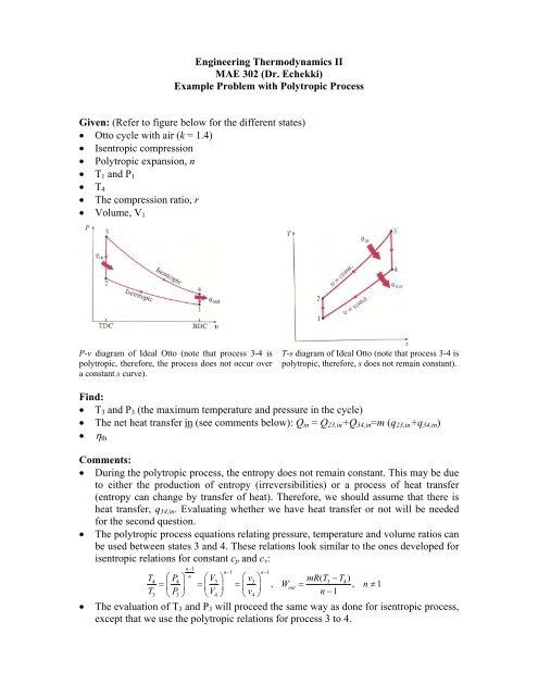
pV diagram of Otto Cycle. The area bounded by the complete cycle path represents the total work that can be done during one cycle. The Otto cycle is often plotted on a pressure-volume diagram (pV diagram) and a temperature-entropy diagram (Ts diagram).When plotted on a pressure-volume diagram, the isochoric processes follow the isochoric lines for the gas (the vertical lines), adiabatic ... The actual exhaust and intake stroke has been replaced by process 4–1, as described in Section IV.A. Representation of the Otto cycle on a pressure–volume (PV) diagram and temperature–entropy (TS) diagram is provided in Fig. 2. FIGURE 2. Process diagrams for the Otto cycle. Access 130+ million publications and connect with 20+ million researchers. Join for free and gain visibility by uploading your research. otto cycle, otto cycle in hindi, otto cycle derivation, otto cycle pv and ts diagram, thermodynamicsintroduction to Thermodynamics, System and Its Types- htt...
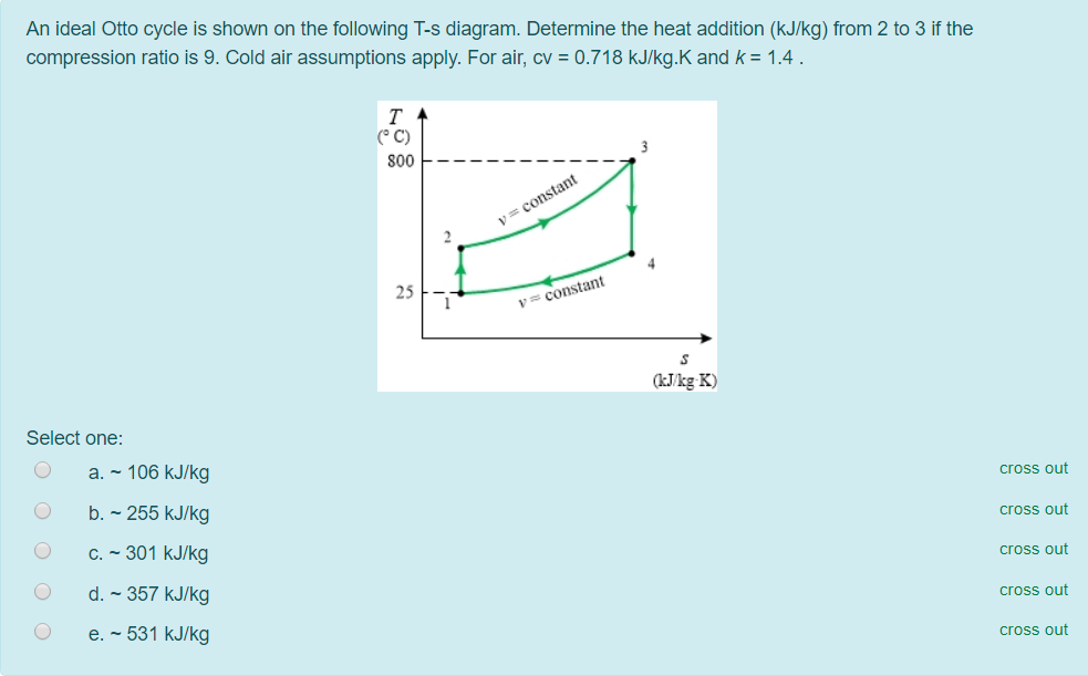
Therefore first let us see an overview of an Otto cycle with the help of PV diagram and TS diagram as displayed here in following figure. As we can see in below figure, there will be two isentropic or adiabatic processes and two constant volume processes. We will determine the various properties for unit mass of working fluid.

Ts Diagram Of A Brayton Gas Power Cycle With Intercooling Natural Philosophy Brayton Cycle Mechanical Engineering
November 3, 2012 - Error. Page cannot be displayed. Please contact your service provider for more details. (28)
Power cycle 2:OTTO CYCLE. Q.3) Draw Otto Cycle on PV and TS diagram?Write formula for its efficiency. Ans : The air-standard-Otto cycles is the idealized cycle for the spark-ignition internal combustion engines (SI engines or Petrol Engines).This cycles is shown above on P-V and T-S diagrams.
Application of Otto Cycle. Otto Cycle is used in all two-stroke and four-stroke petrol engines of motorcycles, cars and in other light-duty vehicles. This is the information about the Otto Cycle and Otto Cycle T-S diagram and Otto Cycle P-V diagram. We hope this information will help you.
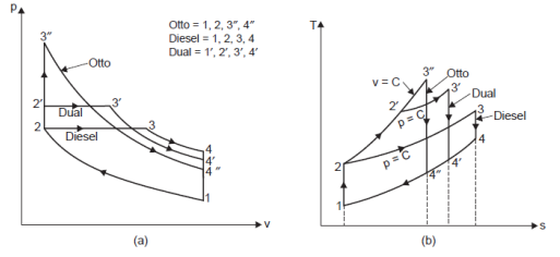
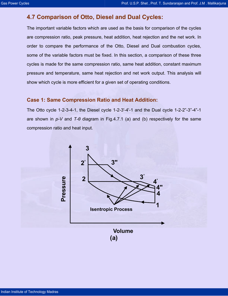
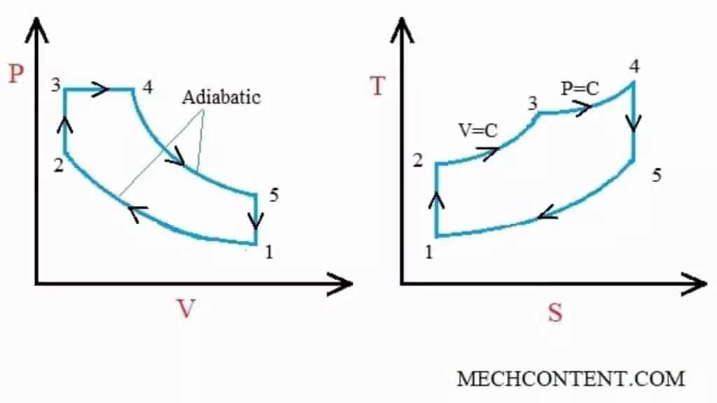
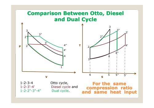
Draw Superimposed P V Diagram Of Otto Cycle Diesel Cycle And Dual Cycle To Compare Their Efficiencies For Same Compression Ratio R C And Heat Rejection Q R Mechanical Engg
Otto cycle The Otto Cycle is named after Nikolaus Otto (1832-1891, German) who is credited as the first creator of a petroleum fuel based internal combustion engine operating under a four stroke cycle. Otto's engine work during the eve of the industrial revolution was a critical development leading to the dawn of the automotive industry in the late 19th century.
March 3, 2017 - Answer (1 of 2): The above diagram is the T-S diagram for an Otto cycle. Process 1–2 - This represents the isentropic compression process. It is carries out reversibly and adiabatically i.e. isentropically. So the entropy remains constant. The temperature changes according to the relation - T_...
Efficiency of the Otto Cycle vs. Carnot Cycle • There are only two temperatures in the Carnot cycle • Heat is added at T H ... State Diagrams for the Diesel Cycle. Diesel Cycle Otto Cycle The only difference is in process 2-3. Consider Process 2-3 • This is the step where heat is transferred into the
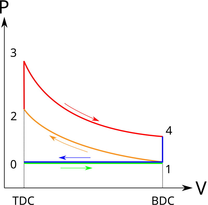
PV and TS diagram of Otto cycle. Intake Stroke (Green line): In this stroke, the piston sucks air and petrol mixture into the combustion cylinder by moving from TDC to BDC. During the piston's movement toward the BDC, the chamber volume increases due to that a vacuum creates inside the chamber.
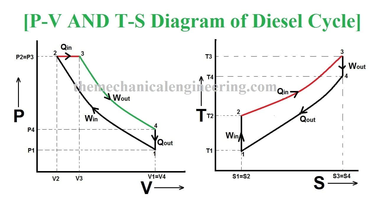
Diesel Cycle - Process with P-V and T-S Diagram. The diesel cycle was invented by Rudolph Diesel in 1893. He put forward an idea by which we can attain higher thermal efficiency, with a high compression ratio. All diesel engine works on this cycle. Diesel is used as fuel in this cycle as it can be compressed at higher compression ratio.
Access 130+ million publications and connect with 20+ million researchers. Join for free and gain visibility by uploading your research.
An Otto cycle is an idealized thermodynamic cycle that describes the functioning of a typical spark ignition piston engine.It is the thermodynamic cycle most commonly found in automobile engines. The Otto cycle is a description of what happens to a mass of gas as it is subjected to changes of pressure, temperature, volume, addition of heat, and removal of heat.
The Otto cycle is an idealized thermodynamic cycle proposed by Nikolaus August Otto in 1876. This cycle describes the functioning of a typical reciprocating piston engine (see snapshot 4 or the "engine diagram" button). This thermodynamic cycle is used in automobile engines. This cycle consists of two adiabatic and two isochoric transformations.
Answer (1 of 2): The above diagram is the T-S diagram for an Otto cycle. Process 1-2 - This represents the isentropic compression process. It is carries out reversibly and adiabatically i.e. isentropically. So the entropy remains constant. The temperature changes according to the relation - T_...
Anyway the theoretical cico Otto is a good approximation to the real cycle. What Is the 4-stroke Otto Cycle Like? The following diagrams represent the Otto cycle in a 4-stroke engine in both PV and TS coordinates. The thermodynamic transformations that take place during the Otto cycle are: 1-2.
Diesel Cycle is used in two-stroke and four-stroke diesel engine. The diesel cycle produces more amount of power compared with less fuel to the Otto cycle. The diesel engine is used in heavy vehicles like Car, Trucks, Generator, and Buses extra. The fuel system is larger here but where in Otto cycle has smaller.
The Otto cycle is often plotted on a pressure- volume diagram ( pV diagram) and on a temperature-entropy diagram (Ts diagram). When plotted on a pressure volume diagram, the isochoric processes follow the isochoric lines for the gas (the vertical lines), adiabatic processes move between these vertical lines and the area bounded by the complete ...
The Otto cycle is often plotted on a pressure-volume diagram (pV diagram) and a temperature-entropy diagram (Ts diagram). When plotted on a pressure-volume diagram, the isochoric processes follow the isochoric lines for the gas (the vertical lines), adiabatic processes move between these vertical lines, and the area bounded by the complete ...
p3 / p2 = r ^ gamma. T3 / T2 = r ^ (gamma - 1) where p is the pressure, T is the temperature, and gamma is the ratio of specific heats. During the combustion process (3-4) , the volume is held constant and heat is released. The change in temperature is given by. T4 = T3 + f * Q /cv. where Q is the heat released per pound of fuel which depends ...
The Carnot Cycle describes the operation of refrigerators, the Otto Cycle describes the operation of internal combustion engines, and the Brayton Cycle describes the operation of gas turbine engines. P-V and T-s diagrams are often used to visualize the processes in a thermodynamic cycle and help us better understand the thermodynamics of engines.
P-v and T-s Diagram of Diesel Cycle. Let the engine cylinder carry m kg of air at point 1. at this point let P1 and T1 and V1 be the pressure, temperature and volume of the air. Following are 4 stages of an ideal diesel cycle. The ideal diesel cycle consists of two adiabatic, constant pressure and constant volume processes.
The entire modern petrol engine works on Otto cycle. It consist of four processes, Two isentropic (reversible adiabatic) processes and two isochoric (constant ...4: 4-1: Constant Volume Heat Rejection1: 1-2: Isentropic Compression2: 2-3: Constant Volume Heat Addition3: 3-4: Isentropic ExpansionHow Otto Cycle Works? · Constant Volume Heat Rejection
It is description of cycle diagram of the otto, diesel and dual cycle.. Hope you like it.
The diesel cycle has high thermal efficiency. 2. It has a low compression ratio. But This one works on a high compression ratio. 3. Otto cycle is also called a Constant volume cycle. The diesel cycle is called a constant pressure cycle. 4. Otto cycle system is light in weight.
April 22, 2012 - An ideal air-standard Otto cycle engine has a compression ratio of 8. At the beginning of the compression process, the working fluid is at 100 kPa, 27°C (300 K), and 800 kJ/kg heat is supplied during the constant volume heat addition process. Neatly sketch the pressure-volume [ ... ] diagram for ...
Otto Cycle Ts Diagram. otto cycle processes with p v and t s diagrams introduction to otto cycle processes in otto cycle p v and t s diagrams for otto cycle with animation video of petrol engine what is otto cycle p v and t s diagram easiest the otto cycle was given by dr nikolaus august otto mechanical booster a mechanical engineering blog p v and t s diagram easiest explanation
Fig.1 shows the limitation of the maximum cycle temperature due to heat leakage in the temperature-entropy diagram of an air standard Otto cycle model.
An air standard Otto-cycle model with heat resistance, heat leak and internal irreversibility coupled to two constant temperatures, one at hot reservoir T H and other at cold reservoir T is shown ...
May 1, 2019 - Otto cycle is a thermodynamic cycle upon which a spark ignition engine works. SI engine uses petrol fuel. Otto cycle was invented by Nicolas Otto in 1876.











Comments
Post a Comment