39 adc block diagram
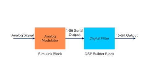
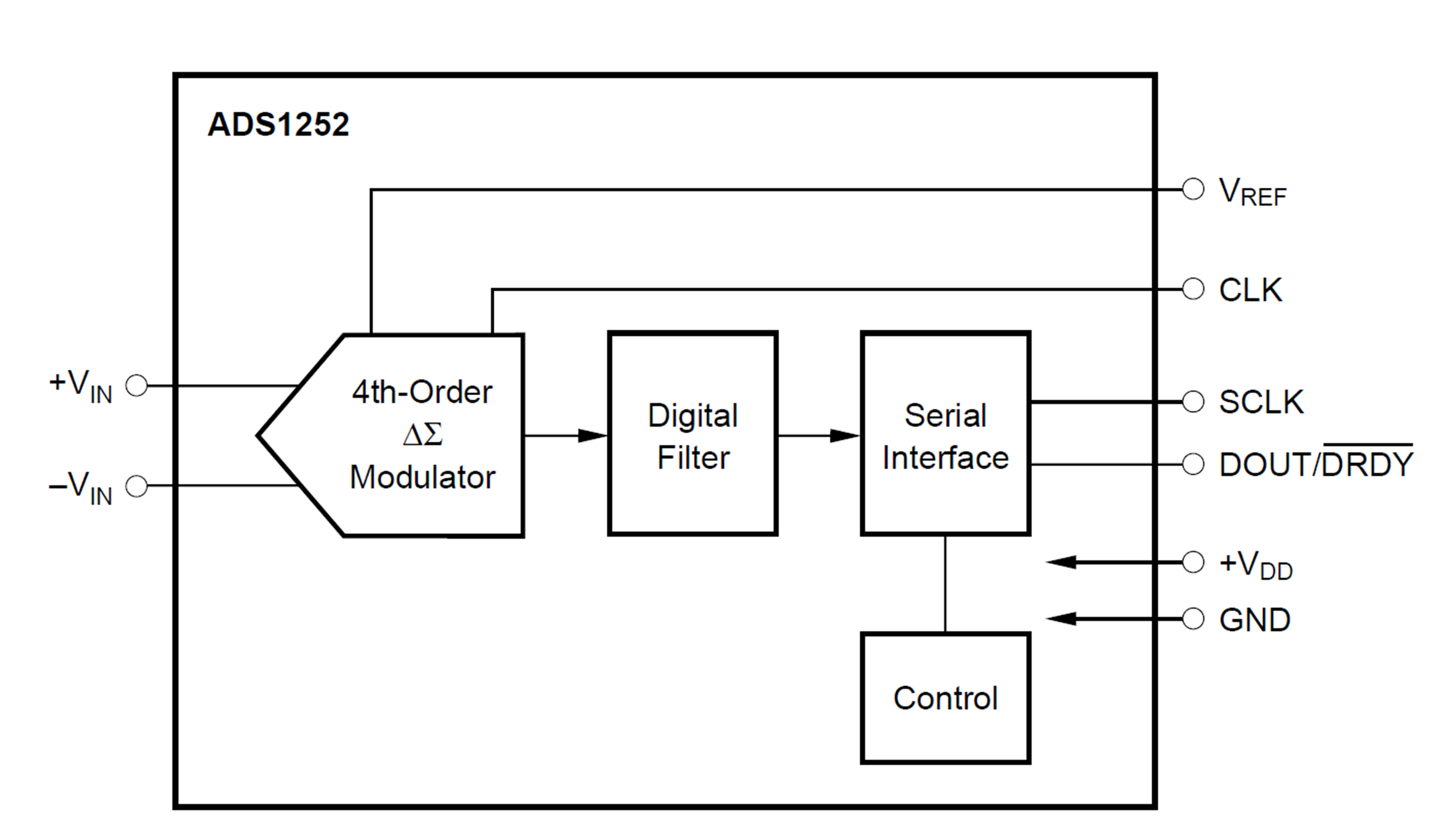
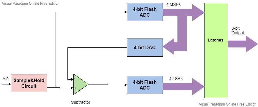
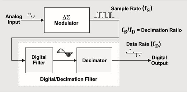
adc block diagram - Cortex-M Attachment: adc block diagram. 8-bits ADC block diagram. Next item TI TM4C123 ADC Block. Started July 23, 2016 3686 0 0. 8-bits ADC block diagram Add Comment. Cancel reply. Your email address will not be published. Required fields are marked * Your Message. Name. Email. Website. Continuous-Time Sigma-Delta ADCs: the "Alias-Free" ADC - News Block Diagram of a Sigma-Delta ADC. As depicted below, a sigma-delta ADC consists of two primary blocks: a sigma-delta modulator and a digital filter. Block diagram of a sigma-delta ADC. Image courtesy of Texas Instruments . With a 1-bit sampling system, the sigma-delta modulator converts the analog input to a high-speed stream of single-bit ...
› sigma-delta-adc-tutorialSigma-Delta ADC Tutorial | Design Center | Analog Devices The diagram inside the applet shows a basic first order sigma-delta modulator. More sophisticated parts may have multiple modulators and integrators however these tend to obscure the underlying sigma-delta principle. Sigma-Delta Modulator Operation. The input voltage V IN is first summed with the output of a feedback DAC. This summing can be ...
Adc block diagram
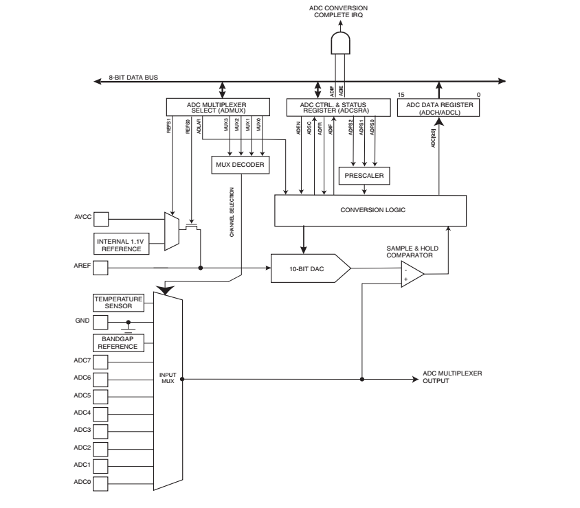
ADC Register Description : Arduino / ATmega328p - Arnab ... The ADC is connected to an 8-channel Analog Multiplexer which allows eight single-ended voltage inputs constructed from the pins of Port A. The single-ended voltage inputs refer to 0V (GND). ATmega328P ADC Block Diagram. The ADC uses registers ADMUX, ADCSRA, ADCL, ADCH, ADCSRB, and DIDR0 to configure the hardware and to do analog to digital ... PDF Pipeline ADC Block Diagram Gain Stage Offset Pipeline ADC Block Diagram 4 Penn ESE 568 Fall 2019 - Khanna adapted from Murmann EE315B, Stanford Remainder Residual Gain Stage Offset ! Input referred converter offset - usually no problem ! Equivalent sub-ADC offset - easily accommodated through redundancy 5 Penn ESE 568 Fall 2019 - Khanna adapted from Murmann EE315B, Stanford PDF ADC Block Diagram External Input Pin Descriptions ADC Block Diagram Chapter8 Analog-to-Digital Converter (ATD10B8C) Block Description 224 MC9S12C-Family / MC9S12GC-Family Freescale Semiconductor Rev 01.23 8.1.2.2 MCU Operating Modes • Stop Mode Entering stop mode causes all clocks to halt and thus the system is placed in a minimum power
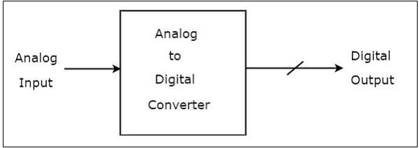
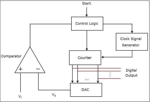
Adc block diagram. PDF 5 Adc Block Diagram ADC BLOCK DIAGRAM Loadcell exitation volatge =5V Loadcell output=2mV/1V,So max load cell out = 10mV Gain of AD8223=14 Filter Gain=0 ADC referance volatge = 5V ADC PGA= 32 ADC SP = 4 0 Reqired resoltion = 18bits Title Size Document Number Rev Date: Sheet of BLOCK DIAGRAM 1.0 OLW A Saturday, January 23, 2016 1 4. 5 5 4 4 3 3 2 2 1 1 D D C C B B A ... Counter type ADC - Tutorialspoint An Analog to Digital Converter (ADC) converts an analog signal into a digital signal. The digital signal is represented with a binary code, which is a combination of bits 0 and 1. The block diagram of an ADC is shown in the following figure −. Observe that in the figure shown above, an Analog to Digital Converter (ADC) consists of a single analog input and many binary outputs. PDF ADC Setup 4/18/22 For reference, a block diagram of the ... For reference, a block diagram of the ADC from page 459. reference [2] Selecting ADC input channels. There is one A/D converter with an analog switch ahead of it that allows selecting the analog source to be used by the converter. There are differential and a single-ended input modes. A ADC USING PIC16F877A - OpenLabPro.com Basically we use this kind of peripherals in the modem. It is a 10 bit ADC module. ADC module of the PIC16F877A controller has a 10-bit resolution output. That means an analog input converted into a corresponding 10-bit digital output and 7 channel ADC. BLOCK DIAGRAM. This is the 10-bit Successive Approximation block diagram.
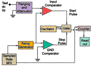
Fundamental Principles Behind the Sigma-Delta ADC Topology ... The Σ- ADC is a staple in the tool kit of today's signal acquisition and processing system designers. The aim of this article is to give the reader the base knowledge on the fundamental principles behind the Σ- ADC topology. Examples of the trade-offs between noise, bandwidth, settling time, and all other key parameters associated with ADC subsyste PDF ANALOG TO DIGITAL CONVERTOR INTERFACE WITH ... - nitrkl.ac.in Fig 4: block diagram for interfacing ADC with 8051 microcontroller 2.1 ALGORITHM FOR PROGRAMMING ADC i) An analog channel is selected by giving bits to A, B, C addresses. ii) ALE(Address Latch Enable) is activated by a low to high pulse in order to latch in the address. PDF Pipeline ADC Block Diagram - University of California ... Pipeline ADC Block Diagram •Idea: Cascade several low resolution stages to obtain high overall resolution (e.g. 10bit ADC can be built with series of 10 ADCs each 1-bit only!) •Each stage performs coarse A/D conversion and computes its quantization Analog to Digital Conversion (ADC) - D&E Notes Figure 1 shows the block diagram of counter type ADC. As shown, it comprises on input voltage comparator a clock generator, a gate and n-bit counter. To begin with, the counter is reset to all 0's. Then a converted signal appears on the start-lie, the input gate is ENABLED and the clock pulses are allowed to the counter's clock input.
Block Diagram Introduction of Switched Capacitor Analog-to ... Block Diagram Introduction of Switched Capacitor Analog-to-Digital Converter (ADC) " As consumer Electronic devices continue to decrease in size and increase in complexity, there is a strong need to integrate more and more functions onto a single chip. There are many reasons for this integration. Board design becomes simpler, fewer devices ... Successive Approximation Register Analog-to-Digital Converter SAR ADC Block Diagram. Chip Layout. Each component in the SAR ADC is outlined in red below. The bootstrap switch, combined with the capacitive digital-to-analog converter (CDAC) comprise a sample-and-hold circuit. The bootstrap switch utilizes feedback to keep the drain to source voltage of the sampling switch constant. › Terminology › DifferenceDifference between ADC types-counter,flash,SAR,dual slope ... SAR(Successive Approximation Register) type ADC. Figure-3 depicts block diagram of SAR type ADC. SAR is the short form of Successive Approximation Register. SAR type ADC is mostly used in digital circuit to provide interface with the microprocessor. In SAR type of ADC, conversion time is uniform for any analog voltage and it is equal to n*T CLK. electrosome.com › adc-pic-microcontroller-hi-tech-cUsing ADC Module of PIC Microcontroller - Hi Tech C Jul 10, 2013 · ADC Block Diagram ADC Module Block Diagram – PIC16F877A Selection of A/D Conversion Clock. The time for A/D Conversion per bit is defined as T AD and it requires minimum 12T AD to generate the 10-bit result. The time T AD is determined by the A/D Conversion Clock which is software selectable to following options. 2 T OSC; 4 T OSC; 8 T OSC; 16 ...
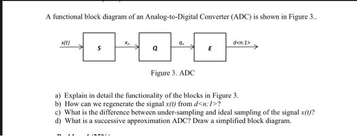
Analog to Digital Converter : Block Diagram, Types & Its ... ADC Block Diagram. The block diagram of ADC is shown below which includes sample, hold, quantize, and encoder. The process of ADC can be done like the following. First, the analog signal is applied to the first block namely a sample wherever it can be sampled at an exact sampling frequency. The amplitude value of the sample like an analog value ...
Adc Block Diagram - 17 images - axi ad9361 analog devices ... Adc Block Diagram. Here are a number of highest rated Adc Block Diagram pictures on internet. We identified it from well-behaved source. Its submitted by government in the best field. We give a positive response this kind of Adc Block Diagram graphic could possibly be the most trending subject next we share it in google improvement or facebook.
PDF Block Diagram of A Digital-analog Converter BLOCK DIAGRAM OF A DIGITAL-ANALOG CONVERTER b1 is the most significant bit (MSB) The MSB is the bit that has the most (largest) influence on the analog output ... The ADC should have more resolution by at least 2 bits and be more accurate than the errors of the DAC
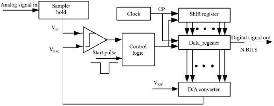
Successive Approximation type ADC | Analog-integrated ... The functional block diagram of successive approximation type of ADC is shown below. It consists of a successive approximation register (SAR), DAC and comparator. The output of SAR is given to n-bit DAC. The equivalent analog output voltage of DAC, VD is applied to the non-inverting input of the comparator.
Learn About SAR ADCs: Architecture, Applications, and ... The simplified block diagram of a SAR ADC is shown in Figure 2. Figure 2 . The sample and hold (S/H) is used to store the input analog value for the conversion phase. The analog comparator compares the S/H output with the analog threshold values generated by the digital-to-analog converter (DAC). As you can see, the output of the comparator is ...
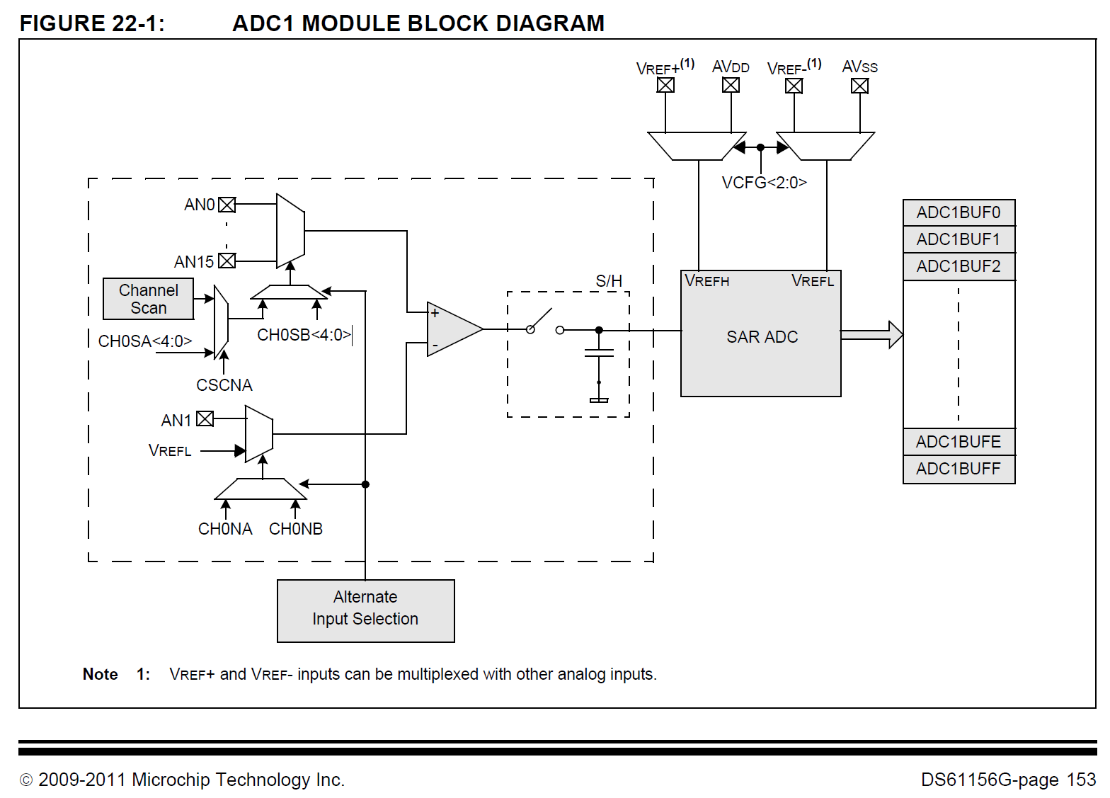
microchipdeveloper.com › 8bit:emr-adcAnalog to Digital Converter (ADC) - Developer Help The Analog-to-Digital Converter (ADC) can convert an analog input signal to a 10-bit binary digital representation of that signal. The Microchip microcontrollers analog inputs, which are multiplexed into a single sample and hold circuit. The output of the sample and hold is connected to the input of the ADC.
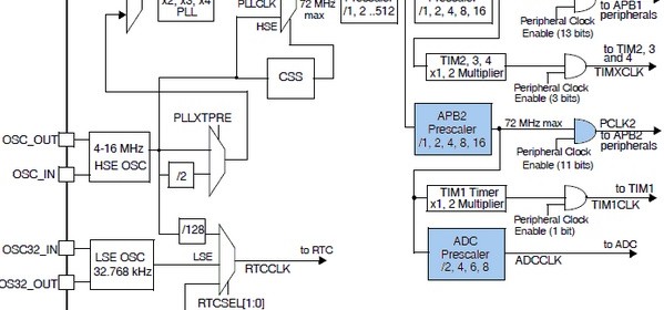
deepbluembedded.com › stm32-adc-tutorial-completeSTM32 ADC Tutorial - Complete Guide With Examples - DMA ... Jun 27, 2020 · ADC Conversion Time & Timing Diagram. the ADC needs a stabilization time of t STAB before it starts converting accurately. After the start of ADC conversion and after 14 clock cycles, the EOC flag is set and the 16-bit ADC Data register contains the result of the conversion. The ADC Analog Watchdog (AWD)
Block Diagram of SAR ADC [15] | Download Scientific Diagram Download scientific diagram | Block Diagram of SAR ADC [15] from publication: confrence paper | In this paper 8 bit SAR ADC with input voltage of 1.2V has been designed. The schematic diagram of ...
electronicsdesk.com › 8086-microprocessorWhat is 8086 Microprocessor? Definition, Block Diagram of ... Block Diagram of 8086 Microprocessor. The architecture of 8086 microprocessor is composed of 2 major units, the BIU i.e., Bus Interface Unit and EU i.e., Execution Unit. The figure below shows the block diagram of the architectural representation of the 8086 microprocessor: Bus Interface Unit (BIU)
PDF Successive approximation ADC - University of Arizona A successive approximation ADC is a type of analog-to-digital converter that converts a continuous analog waveform into a discrete digital representation via a binary search through all possible quantization levels before finally converging upon a digital output for each conversion. Block diagram Successive Approximation ADC Block Diagram Key
Block diagram of the ADC architecture. | Download ... Download scientific diagram | Block diagram of the ADC architecture. from publication: Split-SAR ADCs: Improved linearity with power and speed optimization | This paper presents the linearity ...
electronicscoach.com › cathode-ray-tube-c-r-tWhat is CRT (Cathode Ray Tube)? definition, block diagram and ... The diagram given below shows the internal structure of the CRT. A sharply focused beam is produced by the electron gun assembly. This high-velocity beam strikes the fluorescent screen thus causing a luminous spot on the screen. The two electrostatic deflection plates deflect the accelerated beam by the application of voltage.
PDF Features Functional Block Diagram Adc Dgnd FUNCTIONAL BLOCK DIAGRAM DGND DVDD AGND AVDD REF1 VIN (+) VIN (-) P/S REF2 XTAL CLKIN UNI DB15 DB14 CAL RESET SYNC CS DVAL/RD CFMT/DRDY ... CONTROL LOGIC DB13 AD7722 2.5V REFERENCE DB12 DB11 DB10 DB9/FSO DB0 DB1 DB2 FEATURES 16-Bit - ADC 64 Oversampling Ratio Up to 220 kSPS Output Word Rate Low-Pass, Linear Phase Digital Filter Inherently ...
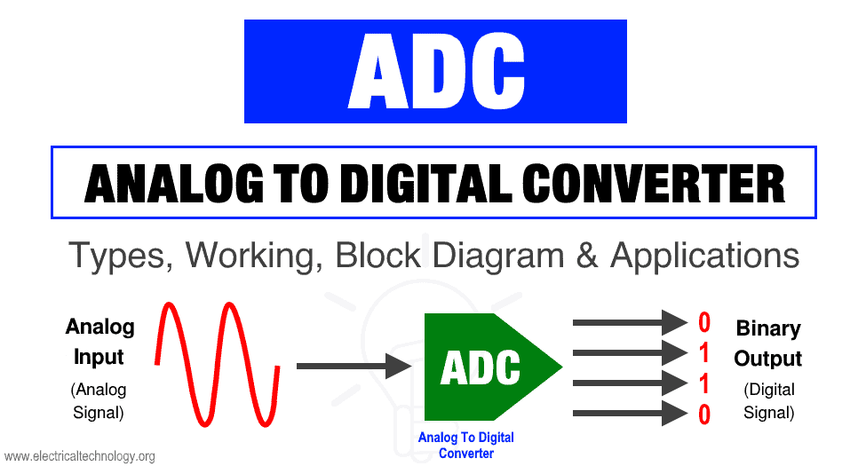
Analog to Digital Converter (ADC) - Block Diagram, Factors ... What is Analog To Digital Converter (ADC)? Block Diagram, Factors & Applications Of ADC What is ADC (Analog To Digital Converter)? ADC stands for analog to digital converter.It is an electronic device used for converting an analog signal into a digital signal.
Solved Problem Set 1 1) By employing | Chegg.com Problem Set 1 1) By employing Matlab-Simulink-Simscape, implement the given ADC block diagram. Logic component parameter settings are given below. Assign 5V to VREFERENCE. Fill up the given table. Most Significant VANALOG (V) 2nd Bit Least Significant Bit (MSB) Bit (LSB) 0 0,65 1,30 1,95 2,60 3,25 3,90 4,55 R=1k02 Comparator VO R102 R=12 R=12 R ...
Successive-approximation ADC - Wikipedia Successive-approximation ADC block diagram showing digital-to-analog converter (DAC), end of conversion indicator (EOC), successive approximation register (SAR), sample and hold circuit (S/H), input voltage (V IN) and reference voltage (V REF)
PDF Figure 2 Block diagram of a previously known flash ADC and ... (a) Block diagram of a flash ADC. (b) Figure 2 Block diagram of a previously known flash ADC and a resistor ladder circuit. Thermometer code to binary encoder Vn V3 V2 V1 Vin D2 D3 Dk D1 gain booster circuit gain booster gain booster gain booster gain booster Figure 1 Block diagram of the proposed TIQ based flash ADC. 3
PDF ADC Block Diagram External Input Pin Descriptions ADC Block Diagram Chapter8 Analog-to-Digital Converter (ATD10B8C) Block Description 224 MC9S12C-Family / MC9S12GC-Family Freescale Semiconductor Rev 01.23 8.1.2.2 MCU Operating Modes • Stop Mode Entering stop mode causes all clocks to halt and thus the system is placed in a minimum power
PDF Pipeline ADC Block Diagram Gain Stage Offset Pipeline ADC Block Diagram 4 Penn ESE 568 Fall 2019 - Khanna adapted from Murmann EE315B, Stanford Remainder Residual Gain Stage Offset ! Input referred converter offset - usually no problem ! Equivalent sub-ADC offset - easily accommodated through redundancy 5 Penn ESE 568 Fall 2019 - Khanna adapted from Murmann EE315B, Stanford
ADC Register Description : Arduino / ATmega328p - Arnab ... The ADC is connected to an 8-channel Analog Multiplexer which allows eight single-ended voltage inputs constructed from the pins of Port A. The single-ended voltage inputs refer to 0V (GND). ATmega328P ADC Block Diagram. The ADC uses registers ADMUX, ADCSRA, ADCL, ADCH, ADCSRB, and DIDR0 to configure the hardware and to do analog to digital ...



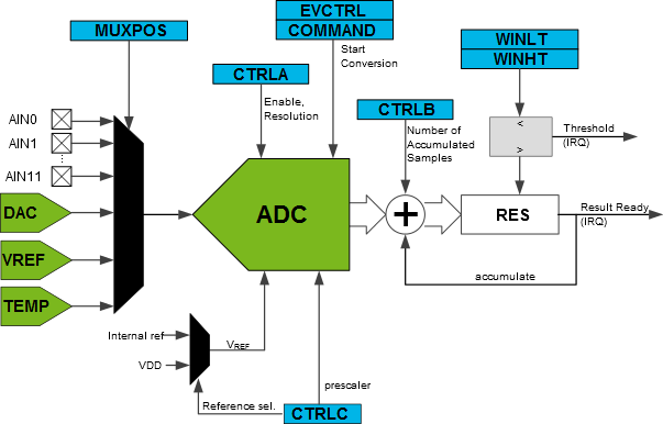
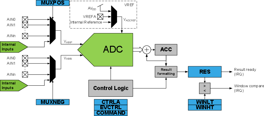








Comments
Post a Comment